
900 S Sedan V6-2498cc 2.5L DOHC (1995)
Before Changing A Control Module
When all checks have been carried out as described in the diagnostic procedure for each diagnostic trouble code or through manual fault diagnosis
without any fault coming to light, it is natural to assume that the control module is defective.
Bearing in mind the fact that the control module is a very expensive high-quality component, it is important to be as sure as possible that your
diagnosis is correct.
Go through the following points very carefully before you definitely decide that the ACC control module is the cause of the fault.
1. Check once again that all points in the diagnostic procedure for the relevant trouble code have been carried out.
2. Study the wiring diagram of the circuit in question and make sure you understand how it works. If necessary, refer to appropriate parts of
the technical description and the description of electrical functions in wiring diagrams.
3. Check all grounding points. If you have already done this, do it again. Check that power ground and signal ground are physically and
electrically separate from each other.
4. Check the power supply for the control module.
5. Go through the points under "General Fault Diagnosis" once again, See: Testing and Inspection
6. If the original fault persists in spite of this, change the ACC control module.
Voltage Supply and Grounding
Power Supply/ground
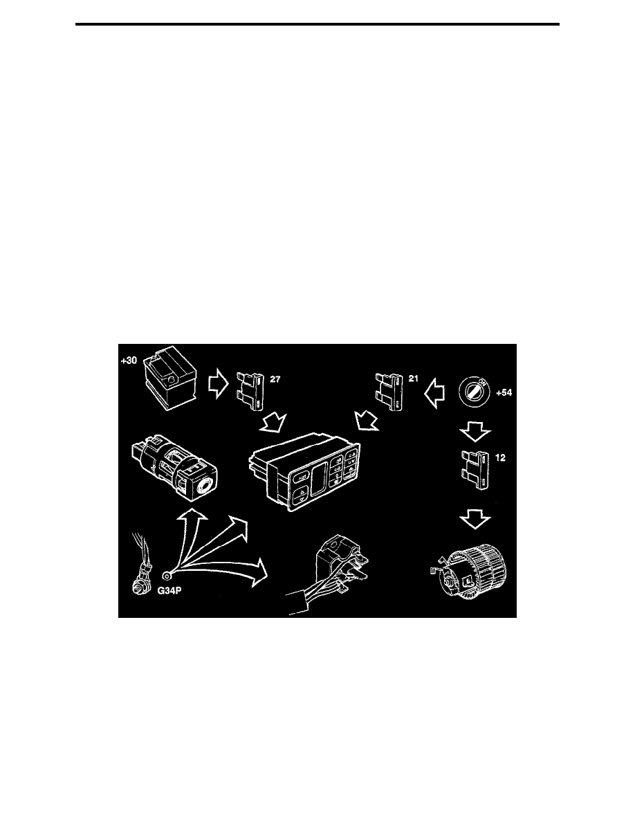
The ACC control module is supplied with power from +30 and +54. The +30 supply provides power and the +54 supply is used to start the ACC
control module. When the starter motor is engaged, no current will be supplied from +54.
Current is applied to pin 22 of the ACC control module from the +30 supply via fuse 27 in fuse holder 22A. Current is applied to pin 4 of the
control module from the +54 supply via fuse 21 in fuse holder 22A.
The ACC control module becomes operational when the power supply is 10 - 16 V. Above or below this voltage range the ACC control module
goes into OFF mode.
The ACC control module, the cabin temperature sensor's suction-fan motor and the fan control share a common ground via the fan control's
connector at grounding point G 34 P.
The ventilation fan is connected to the +54 supply via fuse 21 in fuse holder 22A.