
900 S Sedan V6-2498cc 2.5L DOHC (1995)
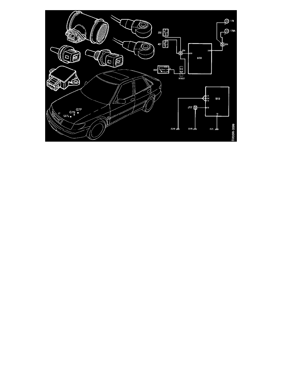
Power Ground, G7P
The control module is connected to power ground via pins 2, 14 and 24. The control module's main ground is applied to pin 14.
Lambda Reference Ground, G7L
The control module's reference ground for Lambda control is applied to pin 10.
Signal Ground, G7S
Pin 19 of the control module is connected to signal ground G7S. Also connected to signal ground are the camshaft and crankshaft position sensors,
and the screening on the oxygen sensors signal leads.
Sensor Ground
The control module grounds pin 30, which is the grounding point for the following sensors:
-
throttle position sensor
-
knock sensors
-
coolant temperature and intake air sensors
-
Mass air flow sensor
Checking of Grounding Points
The difference in potential between the main ground on pin 14 and the sensor ground on pin 30 should be less than about 0.1 V.
A voltmeter can be used to check the control module's main ground by measuring the voltage across pin 14 and the negative battery terminal. A
reading of less than about 0.1 V should be obtained. Other grounding points can be checked in the same manner, but the voltage should be
measured across pin 14 and pins 2, 24,10 and 19. A reading of less than about 0.1 V should be obtained here also.
IMPORTANT: The three ground connections on the ignition coil bracket must always be kept separate.