
900 S Sedan V6-2498cc 2.5L DOHC (1995)
Engine Control Module: Pinout Values and Diagnostic Parameters
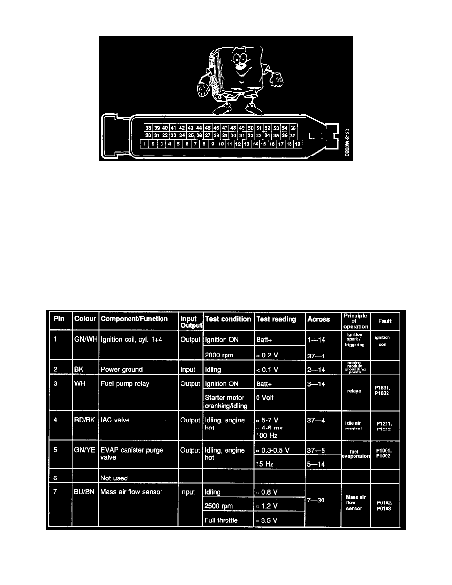
TEST READINGS, CONTROL MODULE CONNECTIONS
Scope
Test readings and instructions for measuring signals and signal levels on the MOTRONIC control module are given in the following charts.
Some Important Points To Remember:
-
Unless otherwise specified, all voltage measurements should be made with all components connected and with the ignition switch in the
DRIVE position.
-
Readings must be taken with a Breakout Box (BOB) connected between the control module and the control module connector.
-
Some readings are to be taken with the engine running at idling speed.
-
Several voltage levels must be regarded as guiding values. Your common sense should tell you whether a reading is correct or not.
-
If any test reading is obviously wrong, use the wiring diagram to trace the leads, connectors or components which you consider ought to be
checked more thoroughly.
NOTE: > greater than; < less than;
~/~ approximately equal to; ~ alternating current
Chart 1 of 4, Pins 1-7