
900 S Sedan V6-2498cc 2.5L DOHC (1995)
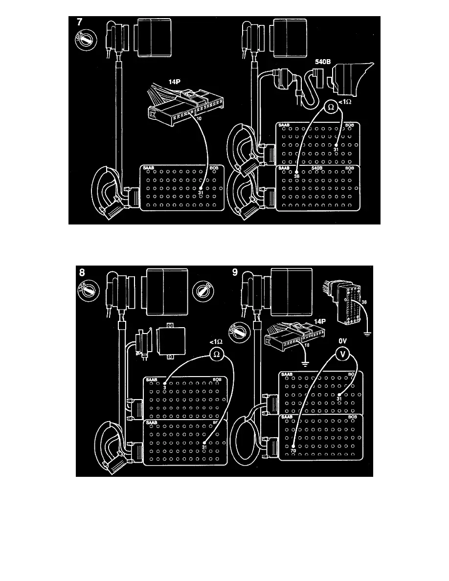
7
If it is not, check the lead for continuity/shorting as follows:
-
between pin 31 of the ICE module connector and pin 10 of the main instrument display panel connector (main instrument display panel 1)
-
between pin 31 of the ICE module connector and pin 38 of the main instrument display panel connector (main instrument display panel 2)
8
If the car is equipped with an anti-theft alarm, also check the lead between pin 31 of the ICE module connector and the anti-theft alarm control
module for continuity/shorting.
9
Unplug the main instrument display panel from the BOB cable. Ground connector pin 10 (main instrument display panel 1) or pin 38 (main
instrument display panel 2) and then repeat point 6.
If the voltage reading is OK, continue fault diagnosis as described in "Main instrument display panel". See: Instrument Panel, Gauges and
Warning Indicators/Instrument Cluster / Carrier/Testing and Inspection
If the voltage reading is not OK, proceed to "Before Changing an Electronic Control Module".
Electrically Heated Rear Seat