
900 S Sedan V6-2498cc 2.5L DOHC (1995)
Control Module Power Supply
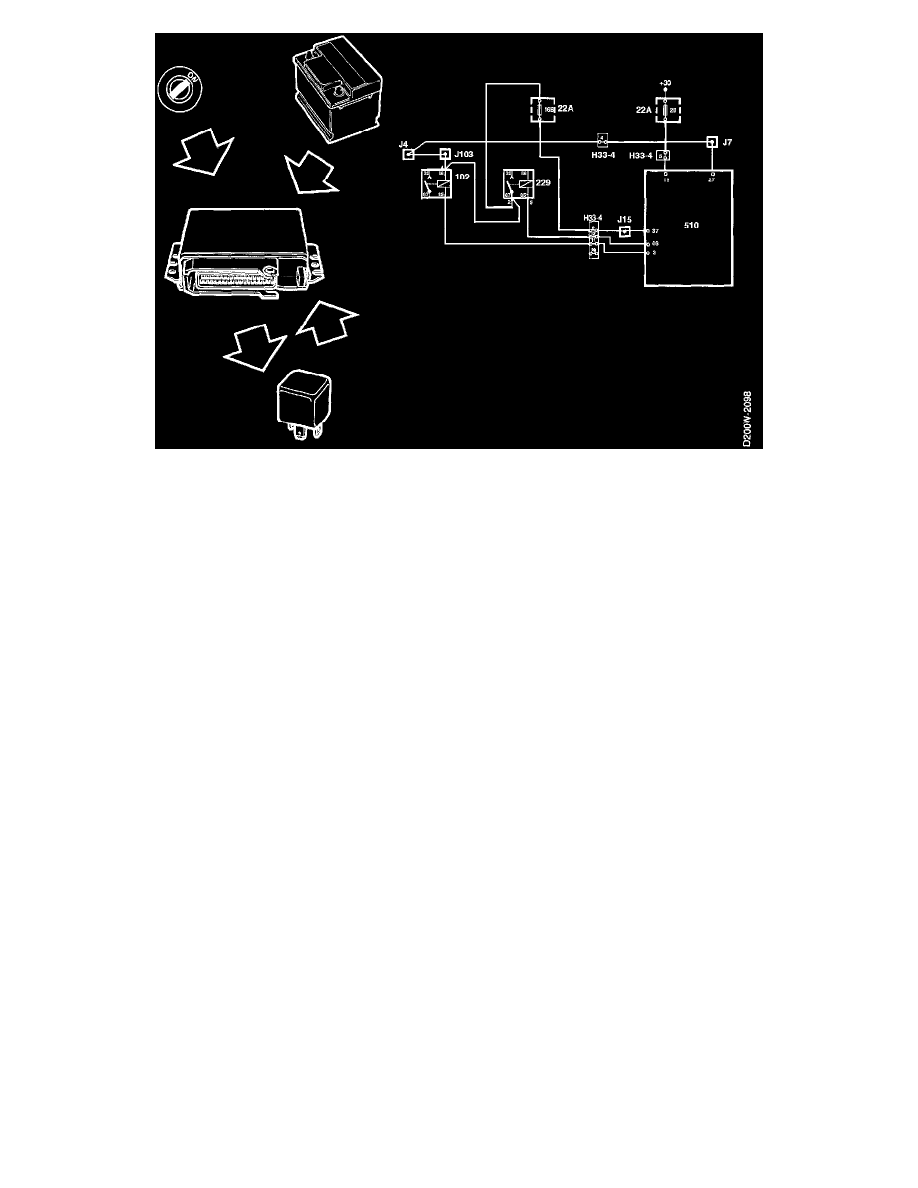
When the ignition switch is turned to the DRIVE position and battery voltage is applied to pin 27 of the control module, pin 85 of the main relay is
grounded via pin 46 of the control module, causing the relay to operate.
The control module then receives its main power supply on pin 37 from pin 87 of the main relay.
NOTE: Counted from the time the ignition is switched OFF, the relay remains in the operated state for another five seconds or so if the
temperature is about 20°C (68°F). At temperatures below 0°C (32°F) the relay may remain in the operated state for up to 30 seconds.
Battery Voltage +30
Battery voltage (+30) is applied to pin 18 of the MOTRONIC control module. The control module uses this voltage to supply the memory with
keep-alive current. Power consumption in the idle state is less than 2.5 mA.
NOTE: Unless the control module is supplied with +30 battery voltage, it will not be possible to start the car.
+15 Voltage
With the ignition switch in the Drive position, a +15 supply is applied to pin 27.
Among other things, the +15 supply is used to activate the control module so that it grounds the main relay, thus enabling a power supply to be
applied to pin 37.