
900 S Sedan V6-2498cc 2.5L DOHC (1995)
Trouble codes present:
Continue with "Fault diagnosis with diagnostic trouble codes".
No trouble codes present:
Continue with "Fault diagnosis with fault symptoms".
2
Some fault diagnosis procedures involve unplugging connectors while the ignition switch is in the ON position. This can give rise to diagnostic
trouble codes. Therefore, when you have finished fault diagnosis, always clear any diagnostic trouble codes that may have been generated. Clear
all diagnostic trouble codes by using the "CLEAR" command.
3
Check fuses 2, 21,17 and 35 as well as MAXI fuse 3.
4
Check all connectors, especially for corroded contact pins, excessive play, loose or retracted pins and anything else that may have an adverse
effect on good electrical contact. If connector trouble is suspected, always spray KONTAKT 61 (part No. 45-30 04 520) contact cleaner into the
female connectors.
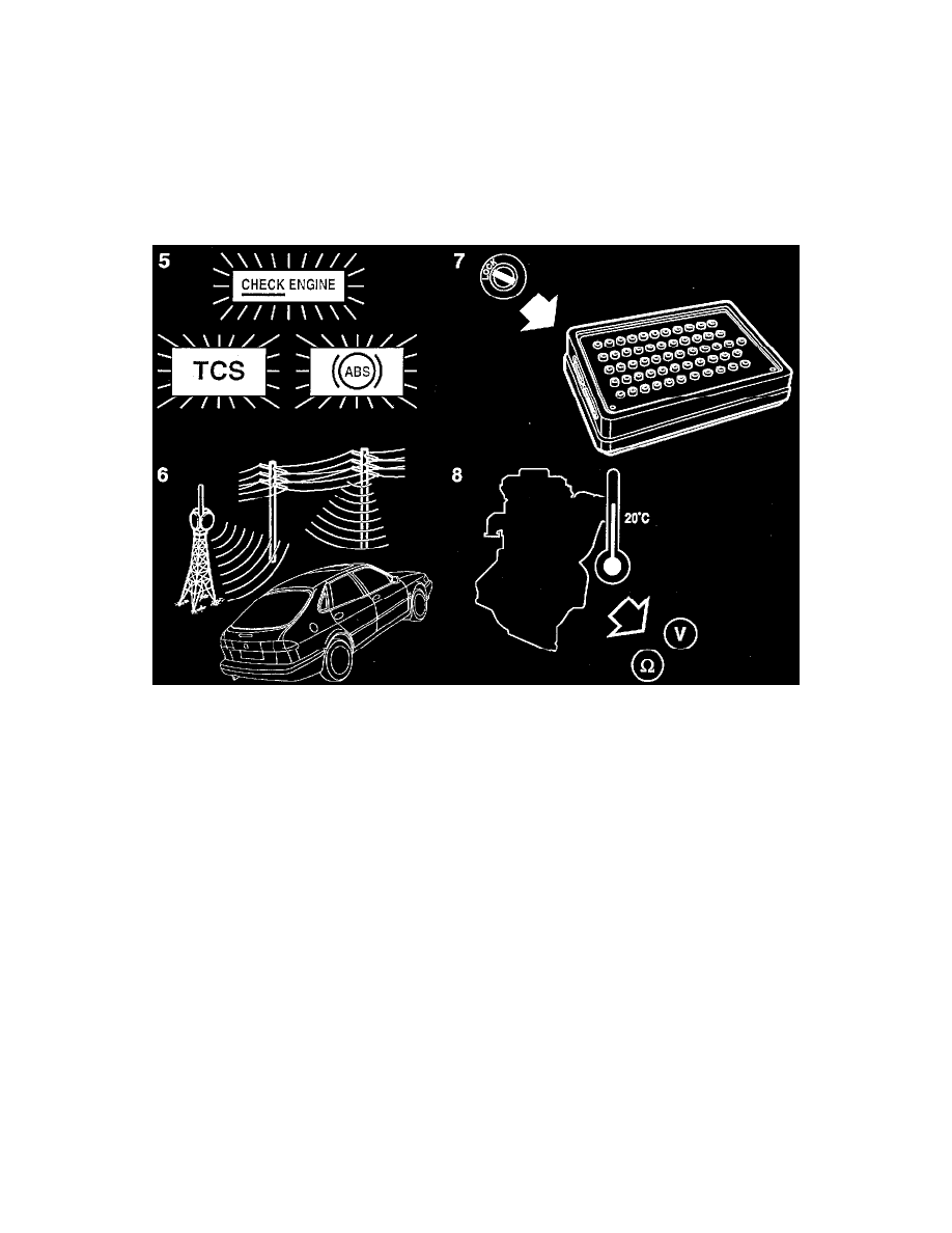
5
Be sure to check whether the "CHECK ENGINE" lamp (MIL) or any other warning lamp is on.
6
Faults may be persistent or intermittent.
A persistent fault continuously meets the fault criteria, i.e. the fault exists only under certain conditions. Examples of such conditions are:
-
Faulty connectors (see point 4).
-
Electromagnetic interference. Interference may consist of electromagnetic radiation emanating from the car's own equipment or from powerful
broadcasting transmitters when the car is driven past radio and TV masts, high-tension transmission lines and places like airports, etc.
-
Faulty components. Switching functions in relays, solenoids, etc. may cause interference through arcing as the contacts make and break.
Intermittent faults require careful analysis to ensure that components in perfect working order are not changed unnecessarily.
7
In general:
-
When connecting a BOB, make sure that the ignition switch is in the OFF position.
-
When unplugging connectors, make sure that the ignition switch is in the OFF position.
-
When taking resistance readings, make sure that the ignition switch is in the OFF position.
8
Measuring the resistance of solenoids and relays.
The nominal resistance is specified at 20°C (68°F). The resistance of the winding is strongly temperature-dependent and increases with rising
temperature.
Exercise caution when judging the results of such resistance measurement.