
900 SE Convertible V6-2489cc 2.5L DOHC EFI (1997)
586
Control module, Motronic
587
Control module, Motronic
588
Solenoid valve, EVAP shut-off
589
Control module, Saab Trionic OBDII
590
Accelerometer
592Fa
Front heated oxygen sensor, 4-cyl, OBDII
592Fb
Front heated oxygen sensor, cylinder bank 1, V6, OBDII
592Ra
Rear heated oxygen sensor, 4-cyl, OBDII
592Rb
Rear heated oxygen sensor, cylinder bank 1, V6, OBDII
593F
Front heated oxygen sensor, cylinder bank 2, V6, OBDII
593R
Rear heated oxygen sensor, cylinder bank 2, V6, OBDII
How to Read and Use Wiring Diagrams
SYMBOLS USED IN THE WIRING DIAGRAMS
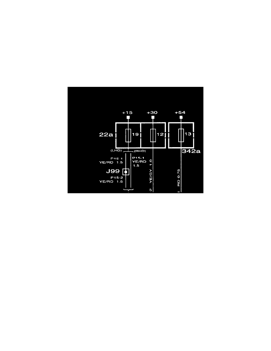
Symbols: Fuses
Fuses
In the wiring diagrams, every subsystem is generally shown from the relevant fuse in the main fuse box up to the respective component or
components and on to the grounding point or direct chassis connection.
The current supplied to each fuse is shown separately in the positive supply system group, which also covers the car's main fuse box, ignition
switch, etc.
Example:
If the current supplied to a fuse comes from the +30 terminal, the circuit incorporating the fuse in question will be found in the "Power supply
(+30 circuit)".