
900 SE Convertible V6-2498cc 2.5L DOHC (1995)
Note
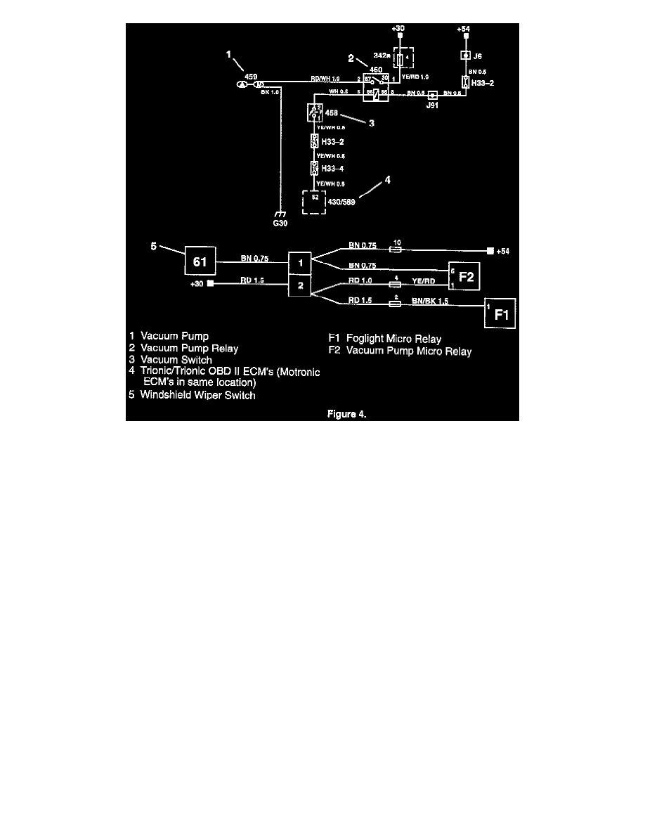
The F2 and F1 designations in Figure 4 refer to the relay location stamped on the bottom of the fuse box cover located under the hood.
1.
Connections in the relay/fuse box:
M1994-95: remove relay holder position F (fog light; will be replaced by two micro relay holders 44 09 934).
Pos F1 = fog light relay
Pos F2 = Vacuum pump relay
Note
The fog light relay will either be a standard size relay (approximately 1x1x1 in.) or a half-size relay. For a standard size relay, follow the instructions
in step 2. For a half-size relay, skip to the instructions in step 3. For these cars, some of the wiring components supplied in the kits will not be used.
2.
Connections for replacing the standard size fog light relay; use adaptor harness (47 39 694) with relay holder (44 09 934).
a.
When fitting wires as indicated in the following steps, be sure to route all of the wires on the bottom side of the relay panel. This will allow
you to just raise the micro fog light relay socket into place when this work is completed.
b.
Remove the Brown/Black 1.5 wire from position 1. Refit this wire in the new micro relay holder position 1.
c.
Remove the two Red/Black 1.0 wires from position 2. Refit these wires into position 2 (micro relay holder).
d.
Remove the Brown/Black 0.5 wire from position 4. Refit this wire in contact housing (91 24 157) position 2.
e.
Remove the Yellow/Red 0.5 wire from position 5. Refit this wire in contact housing (91 24 157) position 1.
f.
Connect the micro relay holder "fog light" with the contact housing (91 24 157).
g.
Fit the pre-wired relay holder (44 09 934) into position F1 and make sure that it is properly secured.