
900 SE Convertible V6-2498cc 2.5L DOHC (1995)
grounding point.
If no voltage reading is obtained, check the lead between fuse 33 and the switch.
9
If a voltage reading is obtained, check the direction indicator switch by connecting a jumper lead between pins 2 and 3 of the connector for the
left-hand direction indicators and between pins 3 and 4 for the right-hand direction indicators.
If the direction indicators work when the pins are connected by jumper leads, the fault is probably in the direction indicator switch. Install a new
switch.
10
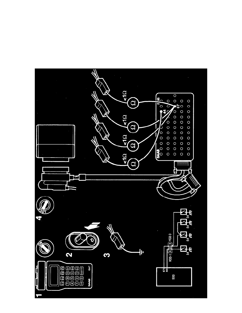
If they do not work, check the leads for continuity/shorting by taking resistance readings as follows:
-
across pin 18 of the ICE control module connector and pin 4 of the direction indicator switch connector.
-
across pin 19 of the ICE control module connector and pin 2 of the direction indicator switch connector.
11
Continue fault diagnosis as described on "Before Changing an Electronic Control Module".
Door Switches