
900 SE Convertible V6-2498cc 2.5L DOHC (1995)
Air Flow Meter/Sensor: Description and Operation
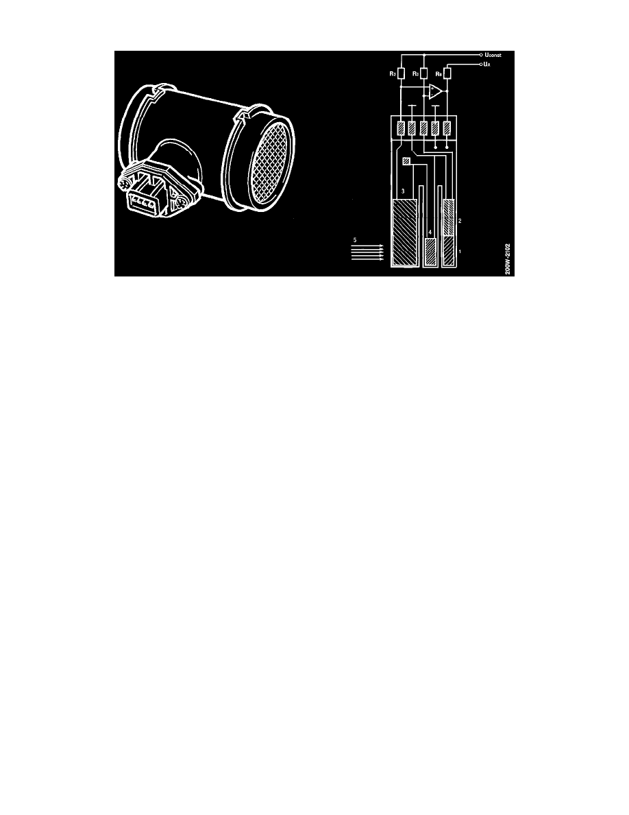
MASS AIR FLOW SENSOR
In the MOTRONIC system an electrically-heated sensor element is encapsulated in plastic. This records the air mass consumed by the engine.
The sensor element consists of a resistive sensor (1), a thermal resistor (2), a temperature sensor (3) and a calibration resistor for the temperature
sensor (4).
The resistive sensor is part of an equalization circuit which conducts current through the thermal resistor in such a way that it always maintains a
constant temperature.
Since the thermal resistor is mounted together with the resistive sensor, it will also maintain a constant temperature.
hen the engine load increases and the mass air flow (5) consequently also increases, its cooling effect on the thermal sensor increases. This forces
the equalization circuit to increase the current (and the temperature) through the thermal resistor.
It will therefore be evident that current consumption through the thermal resistor is determined by the engine load and that the voltage drop which
arises across the resistor is directly proportional to the inlet air mass.
The voltage drop occurs across pins 1 and 4 of the mass air flow sensor and the control module thus receives information via pin 7.
The sensor needs no burn-off function to clean it as is the case with the air mass meter using a filament (hot wire).
Should operation of the mass air flow sensor malfunction for any reason, engine management will be taken over temporarily by the throttle
position sensor which sends information on the position of the throttle to the control module. This results in efficient engagement of the
Limp-Home mode.
The mass air flow sensor can be changed only as a complete unit.