
900 SE Convertible V6-2498cc 2.5L DOHC (1995)
Speedometer Module: Diagram Information and Instructions
Wire Color Code Identification
The Following color code are used in the manual's wiring diagrams. The Color codes may also be used in various combinations such as BU/RD, GY/WH
etc.
CODE
COLOUR
BK
Black
BN
Brown
BU
Blue
GN
Green
GY
Grey
OG
Orange
PK
Pink
RD
Red
VT
Violet
WH
White
YE
Yellow
Ground Distribution
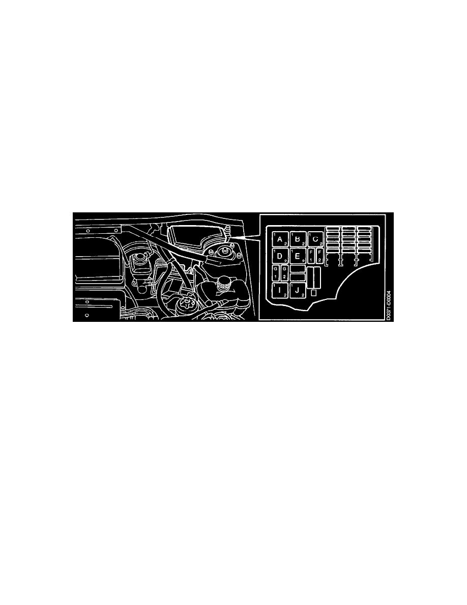
Main Fuse Box, Engine Bay - Main Relay Board (342B)
General Information about Grounding Points
There are two types of grounding points on the car: those having a component number and those where a component is grounded directly to the chassis,
such as a temperature sensor, oil pressure sensor, etc.
The car battery is connected to ground by means of two cables. One has a cross-section area of 25 sq.mm and goes straight to the gearbox (grounding
point G25).
The other has a cross-section areas of 16 sq.mm and goes to grounding point G2, which is located behind the battery on the left-hand wheel housing.
For radio interference suppression, a braided grounding strap is connected between the engine mounting and the car body.
Grounding points having a component number are covered in Diagram Information and Instructions/Ground Information.
NOTE: Since the cars are available in different market versions, certain models might not have some of the grounding points listed.
A component may be connected to different grounding points, depending on whether the car is an Left Hand Drive (LHD) or Right Hand Drive model.
This is indicated in the relevant system schematic.
The connections here apply to LHD cars.
Abbreviations
A number of abbreviations are used in this system. What they stand for is explained in the following table:
Abbreviations
Significance
ABS
Anti-lock Brake System (ABS)