
900 SE Convertible V6-2498cc 2.5L DOHC (1995)
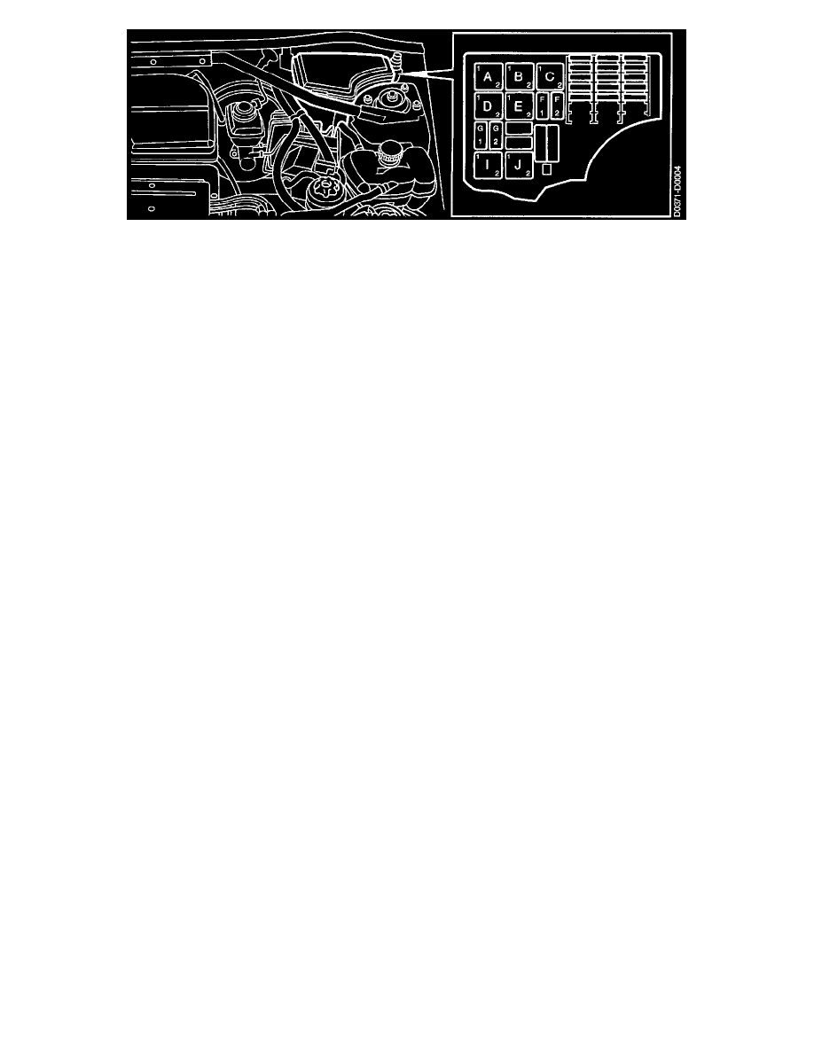
Main Fuse Box, Engine Bay - Main Relay Board (342B)
Loc.
No.
Function
A
8A
Lighting relay
8
8
Main and dipped beam relay
C
524
Secondary air injection pump
D
155
Radiator fan, low speed
E
228B
Filament monitor, headlamps
F1
107
Fog lights
F2
460
Vacuum pump, brake system
G1
68
Horn
G2
549
Secondary air injection control valve
I
81
Radiatorfan, high speed
J
156
Relay, A/C compressor
From SOP, relay 107 for fog lights was a miniature relay on position F. During the model year it has been replaced by a microrelay on position F1.
Cables and Leads
The cables are marked with a cable code consisting of three parts
P15-5 YE/GY 2.5
Where:
The first part is the item number.
The second part is the color code.
The third part is the conductor cross-section area in Sq.mm.
Item Number
Every lead is designated by a letter followed by a number.
Leads with the same number such as E110, E110-1, E110-2 etc, normally
belongs to the same sub-system.
Conductor Cross-Section Area
The cross section area of the conductor is specified in Sq.mm and determines the current the cable is capable of carrying.
Integrated Central Electronics
OPERATION
Because the Integrated Central Electronics (ICE) system is so extensive, only information of a more general nature can be given here.
The ICE is a programmable electronic unit which controls a number of relays as well as sending and receiving information (signals) to and from different
components.
The ICE unit controls the following functions:
^
Main and dipped beams
^
Follow-me-home function
^
Direction indicators, hazard flashers
^
Extra fog lights