
900 SE Sedan L4-1985cc 2.0L DOHC Turbo EFI (1996)
Engine Control Module: Testing and Inspection
General
Scope
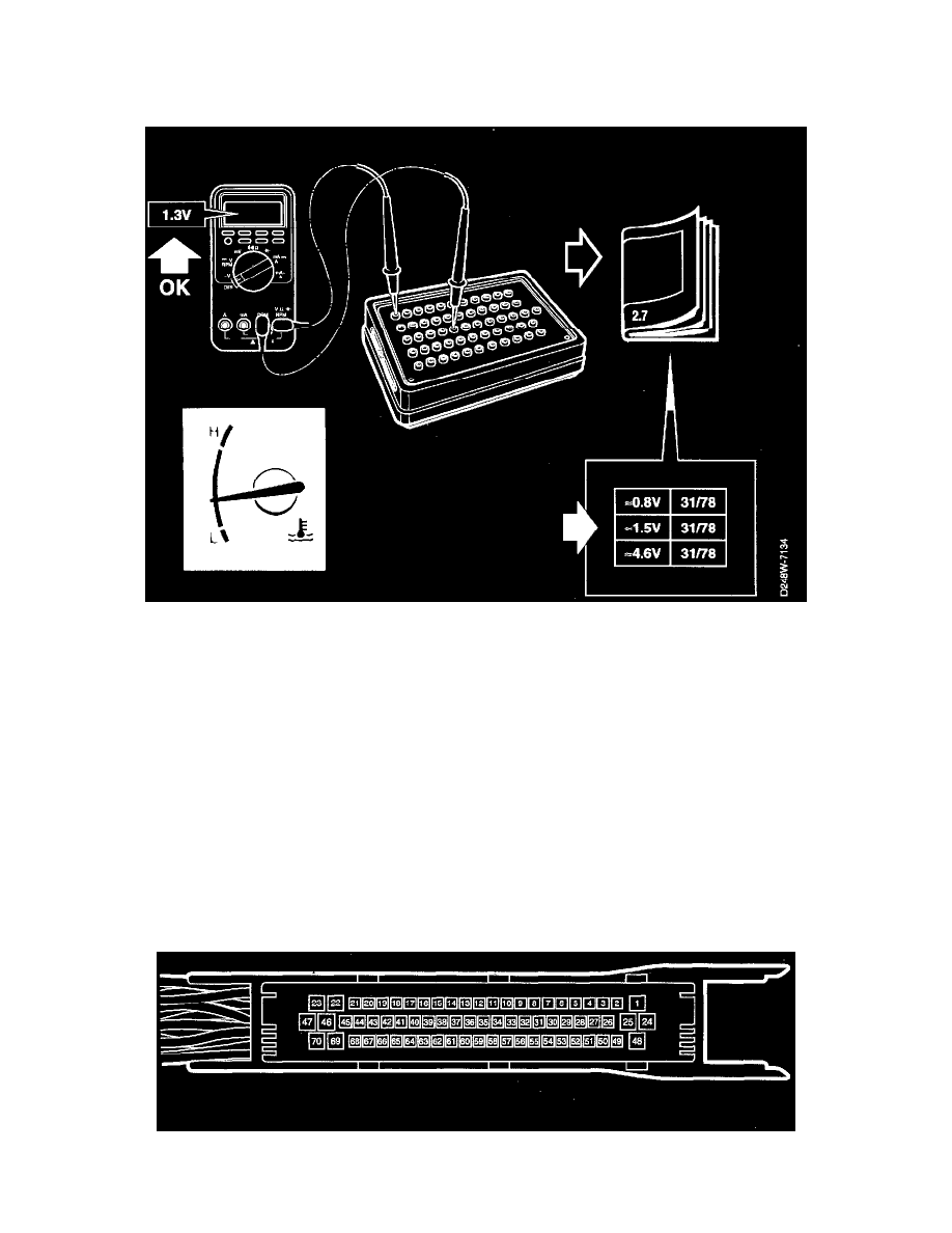
Test readings and directions for measuring signals and signal levels on the Trionic control module are given in the following tables.
Some Important Points To Remember:
^
Readings should be taken with a Breakout Box (BOB) connected between the control module and the control module's connector.
^
Several voltage levels should be regarded as guiding values. Your common sense should tell you whether a reading is correct or not.
^
If any test reading is obviously incorrect, use the wiring diagram to trace the leads, connectors or components which you consider ought to be
checked more thoroughly.
^
The references in the tables at "Function, Fault Diagnosis" contain a description of the relevant signal's function and a fault diagnosis schedule
with detailed, step-by step instructions explaining the diagnostic procedure to be followed.
^
All test readings are for a warmed-up engine.
^
Unless otherwise stated, the ignition should be switched on.
^
The specified test readings are in respect of a calibrated FLUKE 88/97.
> = greater than; < = less than; ~= approximately equal to; ~= alternating current
Pins without further comments are not used.
(LP: LOGIC PROBE P = select pulse; p = visible pulses.)