
900 SE Sedan L4-1985cc 2.0L DOHC Turbo EFI (1996)
Crankshaft Position Sensor: Description and Operation
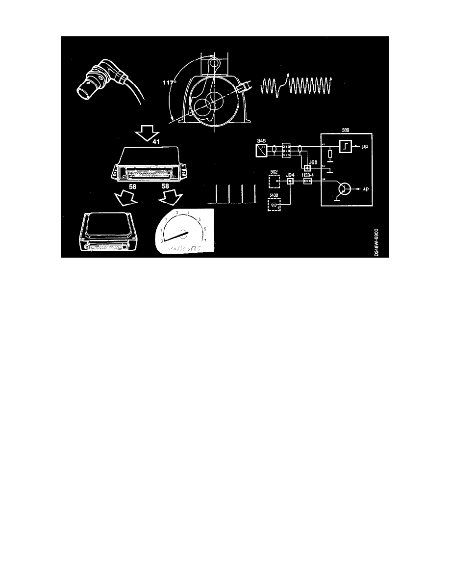
The ECM receives information on the position and speed of the crankshaft from the crankshaft position sensor on pin 41.
A perforated ring with 58 ribs is mounted on the crankshaft. The sensor is of the inductive type and is mounted in the crankcase wall of the engine. The
distance between the sensor and the perforated ring is within the range 0.4-1.3mm and is not adjustable.
The sensor acts as a generator and produces a sinusoidal alternating current. By measuring the frequency, the engine control module can determine the
speed at which the engine rotates (rpm). After the 58th rib is a gap corresponding to 2 ribs. When rib No. 1 subsequently passes the sensor, the engine
control module knows that the crankshaft is 117° before top dead centre (BTDC).
The voltage from the crankshaft position sensor varies with engine speed. During idling the voltage is 7-1 0 V (AC) and at 2500 rpm it is approx. 15-20V
(AC). However, it is the frequency and not the voltage which is of interest to the ECM.
The ECM chiefly uses engine speed and crankshaft position to calculate ignition timing, fuel injection timing, fuel injection time and boost pressure and
for idle speed control.
Fuel injection is cut off when engine speed exceeds 6,400 rpm (6,200 rpm on cars with automatic transmission).
As soon as the ECM receives pulses from the crankshaft position sensor, the ECM grounds the main and fuel pump relays.
If the sensor fails to work or if there is a break in the circuit, the engine will not start.
The sensor's resistance is 540 ± 55 ohms.
Engine Speed Signal
The ECM emits an engine speed signal from pin 58.
The signal is a pulse train which varies between 0 and B+. Its frequency is about 30 Hz at idling speed and about 85 Hz at 2,500 rpm. This corresponds
to 2 pulses per crankshaft revolution.
The engine speed signal is used by the main instrument display panel and the automatic transmission's engine control module.
If the engine speed signal is shorted to ground, the engine can be started but will stop a short time afterwards.