
900 Turbo Convertible L4-1985cc 2.0L DOHC Turbo EFI (1994)
Engine Control Module: Testing and Inspection
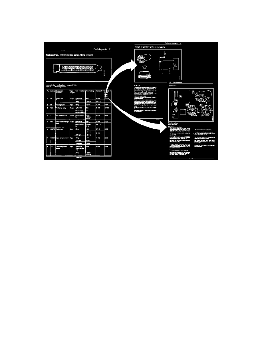
Control Module Connections, Test Readings
Points to Remember
SOME IMPORTANT POINTS TO REMEMBER:
-
Readings must be taken with a Breakout Box (BOB) connected between the control module and the control module connector.
-
Several voltage levels must be regarded as guiding values. Your common sense should tell you whether a reading is correct or not.
-
If any test reading is obviously wrong, use the wiring diagram to trace the leads, connectors or components which you consider ought to be
checked more thoroughly.
-
References in the tables at "Test Readings" refer to the location at which the principle of operation of the signal concerned is described, and
also to the fault diagnosis schedule containing a complete description of the diagnostic procedure to be followed.
Test Reading Charts
POINTS TO REMEMBER
-
The measurements must be performed using a Breakout Box (BOB) connected between the ECM and the ECM's connector.
-
Several voltage levels must be regarded as guide values. Use common sense in assessing whether a measured value is correct or incorrect.
-
If any measured value is incorrect, use the electrical diagram to establish which leads, connectors or components should be checked more closely.
-
The references in the tables relate to the description of the operation of the relevant signal and to the fault diagnosis instructions with a full
description of the diagnostic procedure to be followed.
-
All the measured values apply to a warmed up engine.
-
Unless otherwise stated, the ignition must be switched ON.
-
Indicated measured values relate to calibrated FLUKE 88/97.