
900 Turbo Convertible L4-1985cc 2.0L DOHC Turbo EFI (1994)
Throttle Position Sensor: Description and Operation
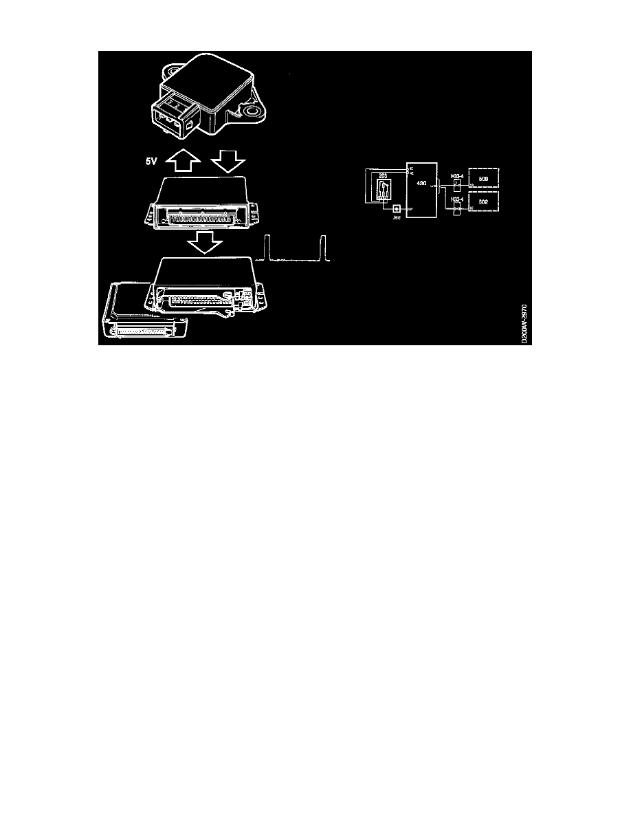
The position sensor consists of a potentiometer connected to the shaft of the throttle plate.
The sensor is supplied with 5 V from ECM pin 42 and is grounded from ECM pin 67. The voltage from the sensor is connected to ECM pin 45
and is proportional to the accelerator setting.
he voltage is approx. 0.5 V during idling and approx. 4.5 V at wide open throttle. The ECM uses the voltage from the sensor to identify idling,
partly open throttle and wide open throttle. During idling the ECM uses a special ignition control matrix and adjusts the idling speed.
The lambda control is disconnected at wide open throttle.
At wide open throttle in connection with starter motor cranking, fuel injection is switched off.
A richer mixture is produced during acceleration and a leaner mixture is produced during deceleration. The maximum boost pressure also depends
on throttle position. If the sensor does not work or if there is an open circuit, the ECM sets wide open throttle as a substitute value and the
malfunction indicator lamp (CHECK ENGINE) in the main instrument lights up.
Throttle Position Signal
The ECM emits a throttle position signal from pin 57. The signal is a PWM signal of 100 Hz and always has a pulse ratio of 9 % during idling
(approx. 1.2 V) and approx. 90 % at wide open throttle (approx. 12 V).
With the ignition switched on and the engine stopped, the pulse ratio is 2-7 % and represents the engine coolant temperature.
The throttle position signal is used by the clutch control module and the automatic transmission control module. The temperature signal is only
used by the automatic transmission control module.