
Aura L4-24L (2008) - Hydraulic Control Assembly - Antilock Brakes Replacement
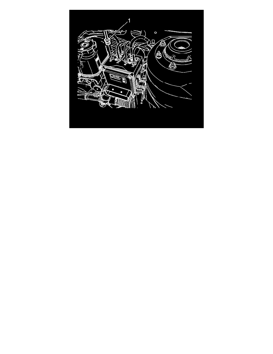
12. Connect the RF brake pipe fitting (1).
Tighten the fitting to 20 N.m (15 lb ft).
Important: Ensure the electrical connector is correctly inserted into the EBCM prior to placing the locking lever into position. Failure to
make a proper connection may cause communication problems with the module.
13. Connect the EBCM electrical connector.
14. Bleed the hydraulic brake system. Refer to Hydraulic Brake System Bleeding (Pressure) (See: Brake Bleeding/Service and Repair)Hydraulic
Brake System Bleeding (Manual) (See: Brake Bleeding/Service and Repair).
Important: Place the ignition switch in the ON position. Do not start the engine.
15. Perform the Diagnostic System Check - Vehicle (See: Testing and Inspection/Initial Inspection and Diagnostic Overview/Diagnostic System
Check - Vehicle).
16. Observe the feel of the brake pedal after performing the diagnostic system check. If the pedal now feels spongy, air may have been in the
secondary circuit of the brake modulator assembly, which may have been introduced into the primary circuit. If the pedal feels spongy, perform the
Antilock Brake System Automated Bleed Procedure (Non-Hybrid Vehicles) (See: Brake Bleeding/Service and Repair).