
Aura L4-2.4L (2008)
‹› If greater than the specified range, test the circuit for a short to ground.
19. If all circuits test normal, replace the BCM.
Repair Instructions
Perform the Diagnostic Repair Verification (See: Testing and Inspection/Diagnostic Trouble Code Tests and Associated Procedures/Verification Tests
and Procedures) after completing the repair.
*
Control Module References (See: Testing and Inspection/Programming and Relearning) for module replacement, setup, and programming
*
GMLAN Wiring Repairs (See: Testing and Inspection/Component Tests and General Diagnostics)
Scan Tool Does Not Communicate with Low Speed GMLAN Device (Buss 2)
Scan Tool Does Not Communicate with Low Speed GMLAN Device (Buss 2)
Diagnostic Instructions
*
Perform the Diagnostic System Check - Vehicle (See: Testing and Inspection/Initial Inspection and Diagnostic Overview/Diagnostic System
Check - Vehicle) prior to using this diagnostic procedure.
*
Review Strategy Based Diagnosis (See: Testing and Inspection/Initial Inspection and Diagnostic Overview/Strategy Based Diagnosis) for an
overview of the diagnostic approach.
*
Diagnostic Procedure Instructions (See: Testing and Inspection/Initial Inspection and Diagnostic Overview/Diagnostic Procedure Instructions)
provides an overview of each diagnostic category.
Diagnostic Fault Information
Circuit/System Description
Modules connected to the low speed GMLAN serial data circuit monitor for serial data communications during normal vehicle operation. Operating
information and commands are exchanged among the modules when the ignition switch is in any position other than OFF. The low speed GMLAN serial
data circuit must be operational for the vehicle to start so the vehicle theft deterrent (VTD) module and body control module (BCM) can communicate.
The low speed GMLAN serial data circuit uses JX 300 (splice pack comb) as a common connection between some modules and the DLC.
Diagnostic Aids
*
Use the Data Link References (See: Initial Inspection and Diagnostic Overview) to identify the low speed GMLAN serial data modules.
*
This test is used for a total low speed GMLAN communication failure. If only 1 module is not communicating and sets no DTC, ensure that the
vehicle is equipped with the module, then use DTC U0100-U0299 for diagnostics.
*
An open in the low speed GMLAN serial data circuit between the splice pack (comb) and a module(s) will only effect the specific module(s). This
type of failure will set a loss of communication DTC for each module effected, and the other modules will still communicate.
*
An open in the DLC ground circuit terminal 5 will allow the scan tool to operate to set up the vehicle on the tool and then not communicate with
the vehicle. When the scan tool is to the point of communicating with the vehicle, a message on the scan tool will indicate "no CANdi module
detected" and will not communicate.
*
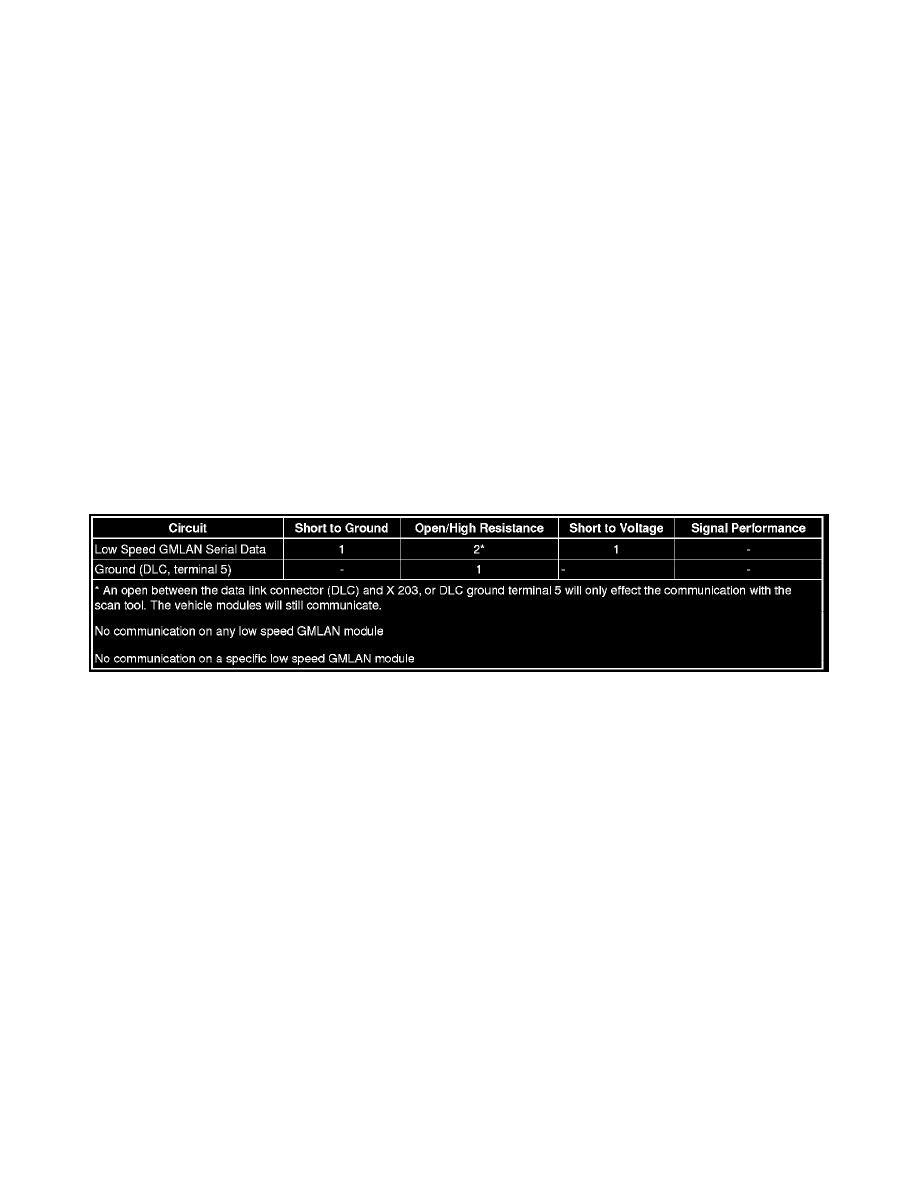
An open between the data link connector (DLC) and X 203 will only effect the communication with the scan tool. The vehicle modules will still
communicate, and the vehicle will start.
*
The engine will not start when there is a total malfunction of the low speed GMLAN serial data circuit.
The following conditions may cause a total loss of low speed GMLAN data communication:
-
The low speed GMLAN serial data circuit shorted to ground or voltage
-
A module internal malfunction that causes a short to voltage or ground on the low speed GMLAN circuit
-
An open in the DLC ground circuit
*
Use the DMM MIN/MAX function to capture/locate intermittent conditions.