
Aura L4-2.4L (2008)
Fuel Injector: Testing and Inspection
Fuel Injector Circuit Diagnosis
Fuel Injector Circuit Diagnosis
Diagnostic Instructions
*
Perform the Diagnostic System Check - Vehicle (See: Testing and Inspection/Initial Inspection and Diagnostic Overview/Diagnostic System
Check - Vehicle) prior to using this diagnostic procedure.
*
Review Strategy Based Diagnosis (See: Testing and Inspection/Initial Inspection and Diagnostic Overview/Strategy Based Diagnosis) for an
overview of the diagnostic approach.
*
Diagnostic Procedure Instructions (See: Testing and Inspection/Initial Inspection and Diagnostic Overview/Diagnostic Procedure Instructions)
provides an overview of each diagnostic category.
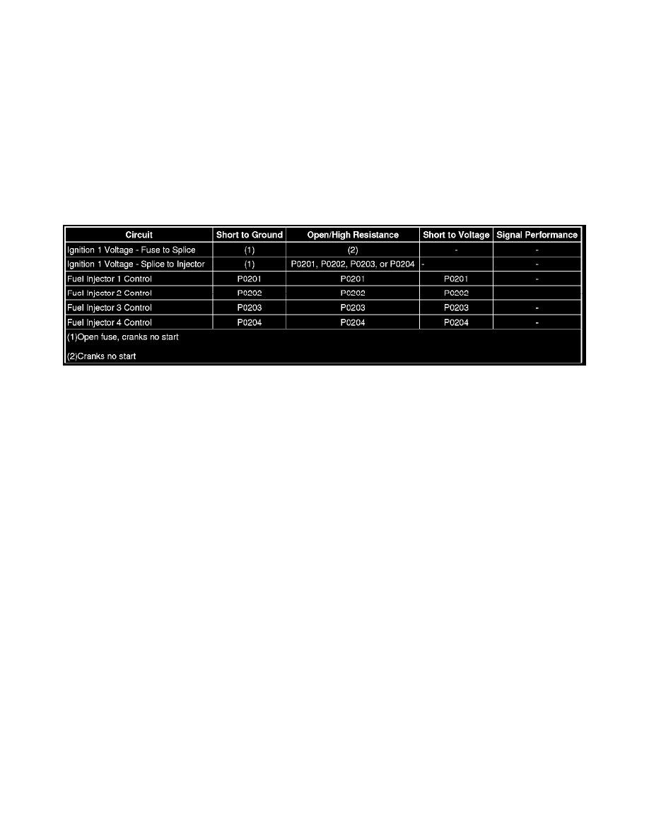
Diagnostic Fault Information
Circuit/System Description
The control module enables the appropriate fuel injector pulse for each cylinder. Ignition voltage is supplied to the fuel injectors. The control module
controls each fuel injector by grounding the control circuit via a solid state device called a driver.
Reference Information
Schematic Reference
Engine Controls Schematics (LAT) (See: Diagrams/Electrical Diagrams)Engine Controls Schematics (LE5) (See: Diagrams/Electrical Diagrams)
Connector End View Reference
Component Connector End Views (See: Diagrams/Connector Views)
Electrical Information Reference
*
Circuit Testing (See: Testing and Inspection/Component Tests and General Diagnostics)
*
Connector Repairs (See: Testing and Inspection/Component Tests and General Diagnostics)
*
Testing for Intermittent Conditions and Poor Connections (See: Testing and Inspection/Component Tests and General Diagnostics)
*
Wiring Repairs (See: Testing and Inspection/Component Tests and General Diagnostics)
Scan Tool Reference
Control Module References (See: Testing and Inspection/Programming and Relearning) for scan tool information
Special Tools
J 44603 Injector Test Lamp
Circuit/System Testing
1. Ignition OFF, disconnect the harness connector at a fuel injector.
2. Ignition ON, verify that a test lamp illuminates between the ignition circuit terminal 1 or A and ground.
‹› If the test lamp does not illuminate, test the ignition circuit for a short to ground or an open/high resistance. If the circuit tests normal and the
ignition circuit fuse is open, test or replace the fuel injector.
3. Ignition OFF, connect a J 44603 between the control circuit terminal 2 or B and the ignition circuit terminal 1 or A of each fuel injector one at a
time.