
Aura L4-2.4L (2008)
Ignition Switch Lock Cylinder: Procedures
Key and Lock Cylinder Coding
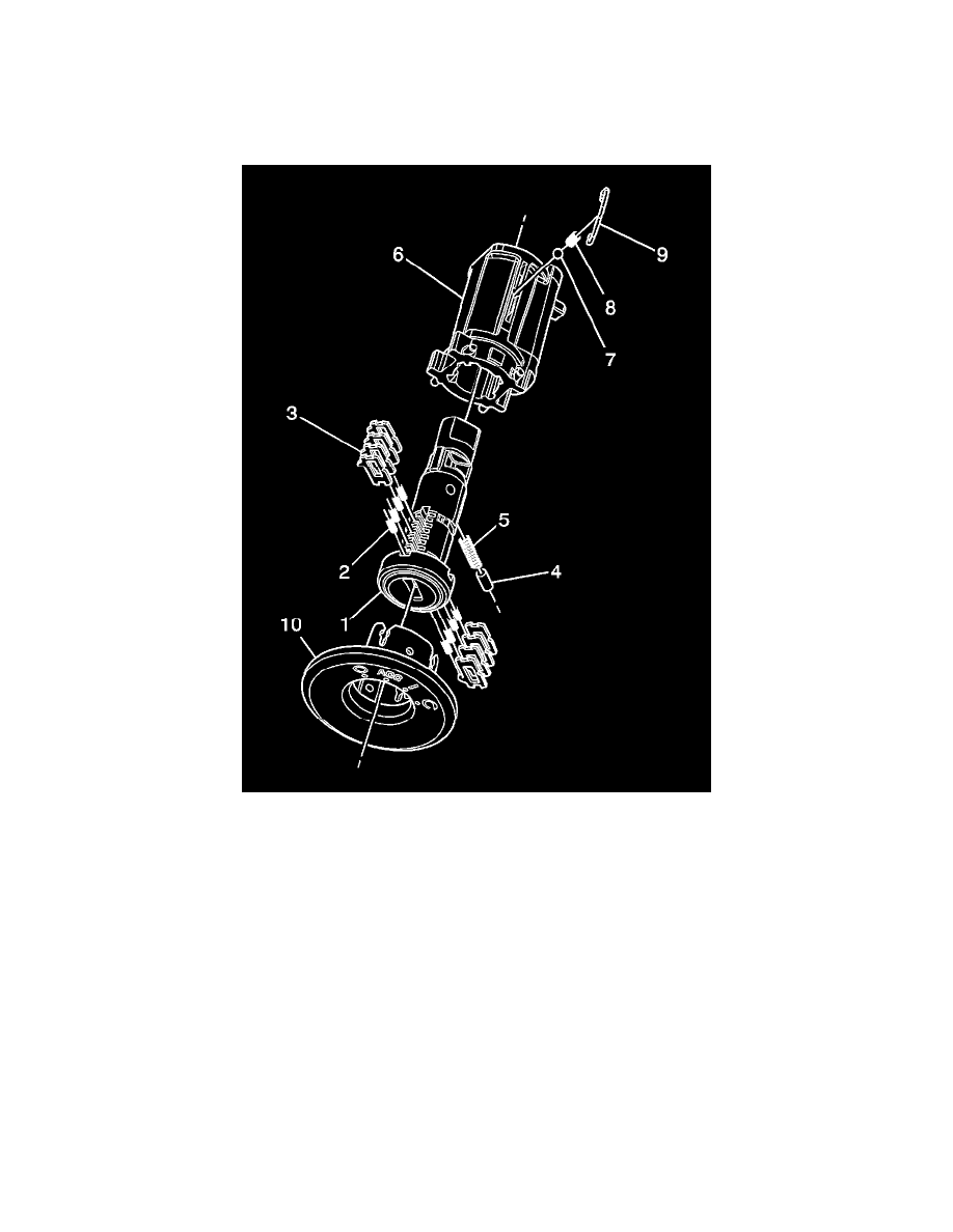
The instrument panel (I/P) ignition lock cylinder uses 8 of the 10 key cut positions, 1-8 when counting from the key head. The tumbler orientations
alternate in adjacent locations from side to side with 4 on each side.
Caution: Wear safety glasses in order to avoid eye damage.
Important: The ignition lock cylinder tumblers (3) are not self-retaining and must be held in place if the key is not fully inserted into the
lock cylinder or until the cylinder (1) is assembled into the case assembly (6).
1. Hold the uncoded cylinder assembly (1) positioned so the side with the retention lug is facing upward.
2. Insert one tumbler spring (2) each into each of the 4 tumbler spring holes.
3. The first tumbler to be loaded will be key cut position 2, the second number in the key code. Determine the cut depth at this position and install the
corresponding tumbler (3) into the tumbler slot nearest the front of the cylinder assembly (1), the end where the key is inserted. It may be
necessary to move the sidebar, already pre-assembled into the uncoded cylinder assembly, out slightly to fully install the tumbler into the correct
slot.
4. In the same manner, determine the cut depth and corresponding tumbler and install the 3 remaining tumblers (3) into the tumbler slots located at
key cut positions 4, 6, and 8.
5. Check for correct loading by holding the tumblers (3) in position and fully inserting the matching key into the cylinder assembly (1). All tumblers
and the sidebar should be flush with the outside diameter of the cylinder assembly.
6. Rotate the cylinder assembly (1) so that the side with the retaining pin (4) hole is facing upward and then remove the matching key. Remember the
tumblers (3) are not self-retaining and must be held in place.
7. Insert one tumbler spring (2) each into each of the 4 tumbler spring holes.
8. The first tumbler to be loaded will be key cut position 1. Determine the cut depth at this position and install the corresponding tumbler (3) into the
tumbler slot nearest the front of the cylinder assembly.
9. In the same manner, determine the cut depth and corresponding tumbler and install the 3 remaining tumblers (3) into the slots located at key cut