
Aura L4-2.4L (2008)
Axle Beam: Service and Repair
Support Replacement
Support Replacement
Tools Required
J 45059 Angle Meter
Removal Procedure
1. Raise and support the vehicle. Refer to Lifting and Jacking the Vehicle (See: Maintenance/Service Intervals).
2. Remove the rear tire and wheel assemblies. Refer to Tire and Wheel Removal and Installation (See: Wheels and Tires/Service and Repair).
3. Remove the muffler. Refer to Muffler Replacement (LAT, LZ4) ()Muffler Replacement (LY7) ().
4. Remove the knuckles. Refer to Knuckle Replacement (See: Front Steering Knuckle/Service and Repair/Rear Suspension).
5. Disconnect the ABS wiring harness from the clips on the support assembly and upper control arms.
6. Position a suitable jack stand under the support assembly.
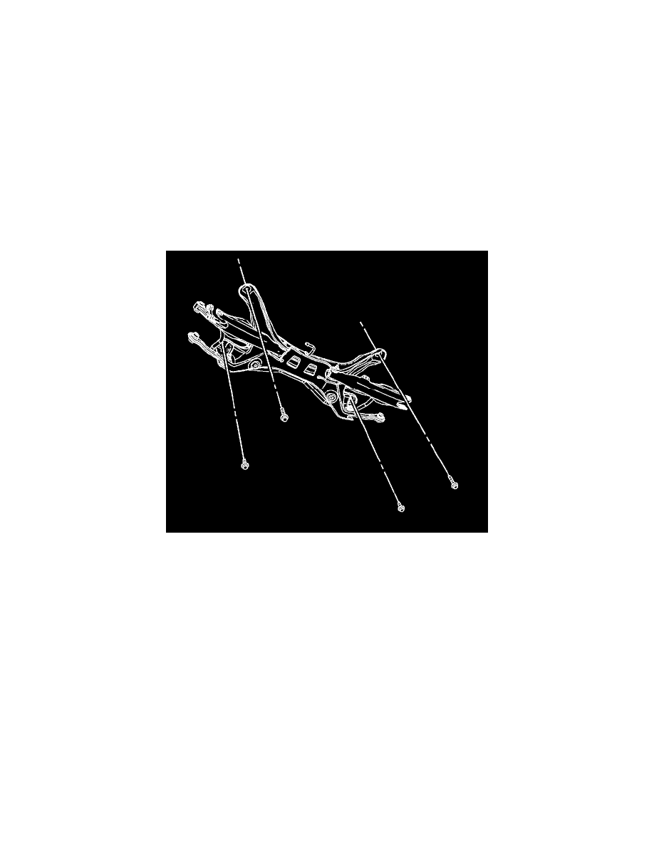
Important: When replacing complete module assembly, mark fastener location of axle bracket (LH/RH) to body rail.
7. Remove the support assembly to body bolts.
Important: Mark location of support assembly to body rails with a dab of paint.
8. With the aid of an assistant, remove the support assembly from the vehicle.
Installation Procedure
Important: If a transfer of components is necessary, it is recommended that the fasteners be loosely installed, then all the suspension
component fasteners be torqued after the support is in the vehicle and all the suspension components installed.
Notice: Refer to Fastener Notice (See: Service Precautions/Vehicle Damage Warnings/Fastener Notice).
1. If a new rear support is being installed, a transfer of components is necessary.
*
Upper Control Arms
Tighten the upper control arm to rear support nut and bolt to 60 N.m (44 lb ft). Using the J 45059, rotate an additional 60 degrees.
*
Lower Control Arms