
ION L4-2.2L VIN F (2004)
7. Install the brake rotor to the hub/axle flange. Use the matchmark made prior to removal for proper orientation to the flange.
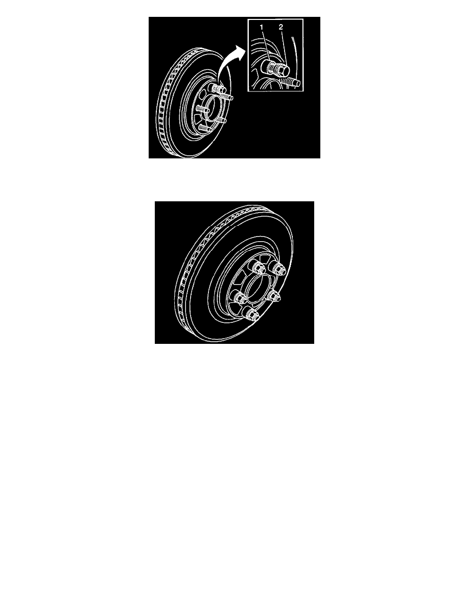
8. Hold the rotor firmly in place against the hub/axle flange and install one of the J45101-100 (1) and one lug nut (2) onto the upper-most wheel stud.
9. Continue to hold the rotor secure and tighten the lug nut firmly by hand.
10. Install the remaining J 45101- 100 and lug nuts onto the wheel studs and tighten the nuts firmly by hand in a star-pattern.
11. Using the J 39544-KIT, or equivalent, tighten the lug nuts in a star-pattern to specification, in order to properly secure the rotor.
12. Measure the assembled LRO of the brake rotor.
13. If the brake rotor assembled LRO measurement still exceeds the maximum allowable specification, refer to Brake Rotor Assembled Lateral
Runout (LRO) Correction.
14. If the brake rotor assembled LRO measurement is within specification, install the brake caliper and depress the brake pedal several times to secure
the rotor in place before removing the J 45101-100 and the lug nuts.
Assembled Lateral Runout (LRO) Correction On-Vehicle Lathe
Assembled Lateral Runout (LRO) Correction On-Vehicle Lathe
-
Tools Required
-
J 45101-100 Conical Brake Rotor Washers
Caution: Refer to Brake Dust Caution in Service Precautions.
Important:
*
Brake rotor thickness variation MUST be checked BEFORE checking for assembled Lateral Runout (LRO). Thickness variation exceeding the
maximum acceptable level can cause brake pulsation.
-
Brake rotor assembled Lateral Runout (LRO) exceeding the maximum allowable specification can cause thickness variation to develop in the
brake rotor over time, usually between 4,800 - 11,300 km (3,000 - 7,000 mi).
1. Ensure that the caliper and caliper bracket that are already being supported, are clear from contacting any rotating components, such as the brake
rotor.
2. Remove the J 45101-100 and the lug nuts that were installed during the assembled LRO measurement procedure and/or the indexing correction
procedure.
3. Inspect the mounting surface of the hub/axle flange and the brake rotor to ensure that there are no foreign particles or debris remaining.
4. Set up the lathe, following the manufacturer's instructions.