
ION L4-2.4L (2007)
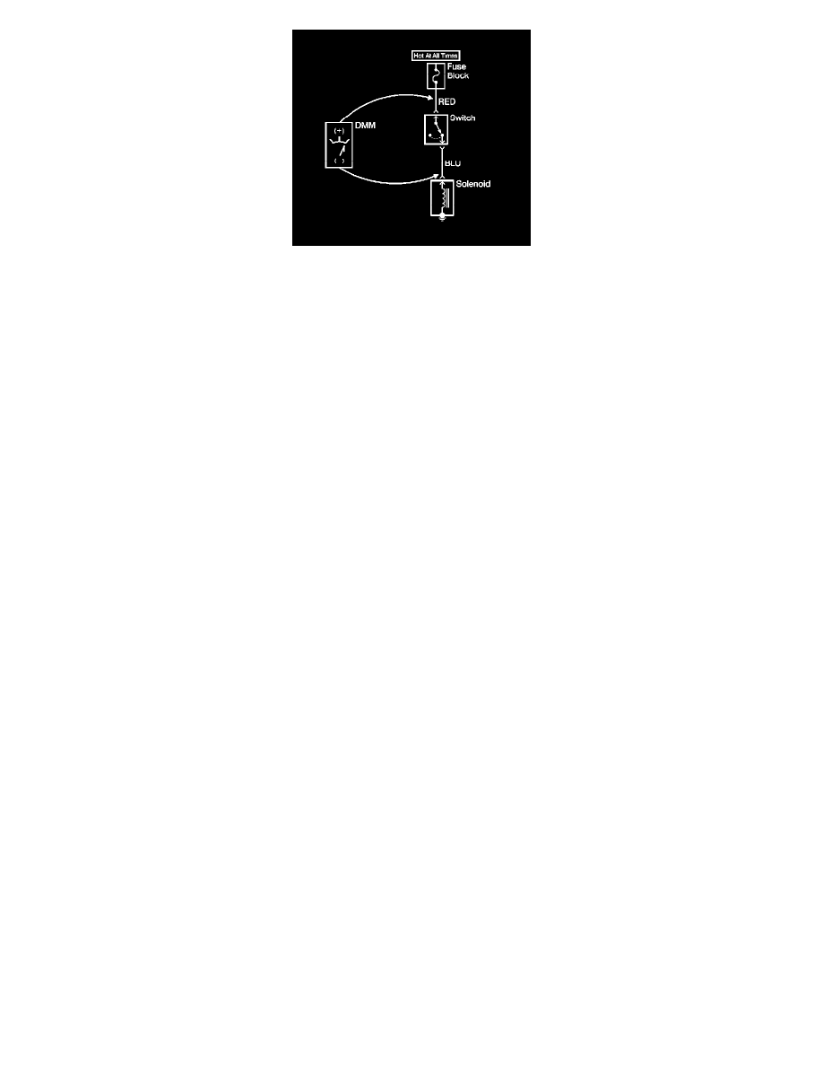
1. Set the rotary dial of the DMM to the V (DC) position.
2. Connect the positive lead of the DMM to one point of the circuit to be tested.
3. Connect the negative lead of the DMM to the other point of the circuit.
4. Operate the circuit.
5. The DMM displays the difference in voltage between the 2 points.
Probing Electrical Connectors
Probing Electrical Connectors
Important: Always be sure to reinstall the connector position assurance (CPA) and terminal position assurance (TPA) when reconnecting connectors or
replacing terminals.
Frontprobe
Disconnect the connector and probe the terminals from the mating side (front) of the connector.
Important: When probing female .64 terminals, it is important to use the correct adapter. There have been some revisions to the test adapter for 0.64
terminals. The proper adapter for .64 terminals is the J 35616-64A which has a tin terminal and a blue wire between the base and tip. Failure to use the
proper test adapter may result in damage to the terminal being tested and improper diagnosis.
Notice: Do not insert test equipment probes into any connector or fuse block terminal. The diameter of the test probes will deform most terminals. A
deformed terminal can cause a poor connection, which can result in system failures. Always use the J 35616 GM-Approved Terminal Test Kit in order to
frontprobe terminals. Do not use paper clips or other substitutes as they can damage terminals and cause incorrect measurements.