
L200 L4-2.2L VIN F (2002)
IMPORTANT: Once the probe is installed, it should not be removed. The diagnostic service probe is designed to stay on the wire permanently. The
gel material inside the probe will seal the wire and allow the wire to be probed several times.
Sneak Circuits
Understanding sneak circuits can help in quickly diagnosing electrical problems that can, at first, seem very complicated.
A sneak circuit can be defined as an unplanned complete circuit. This type of failure is different than a short circuit.
A sneak circuit can occur when more than one component is using the same ground path or power feed. Sneak circuits can happen if a common ground is
lost, a fuse is blown, or a wire is grounded between components.
The most visible sneak circuit on the Saturn vehicle is the headlamp circuit. The headlamp circuits are fed by two fuses, the left headlamp fuse and the
right headlamp fuse. Note that the left headlamp fuse feeds both the high and low beam bulbs on the left side of the vehicle. Likewise, the right headlamp
fuse feeds both the high and low beam bulbs on the right side of the vehicle. On the ground side of the headlamp circuit the important thing to notice is
that both the left and right low beams bulbs are switched on and off together. Likewise, both the left and right high beam bulbs are switched on and off
together.
If the left or right headlamp fuse blows, evidence of the sneak circuit will be the headlamp bulbs on the side of the blown fuse glowing dim yellow. This
is caused by the sneak circuit from the good headlamp fuse, through the bulbs, to ground through the headlamp switch.
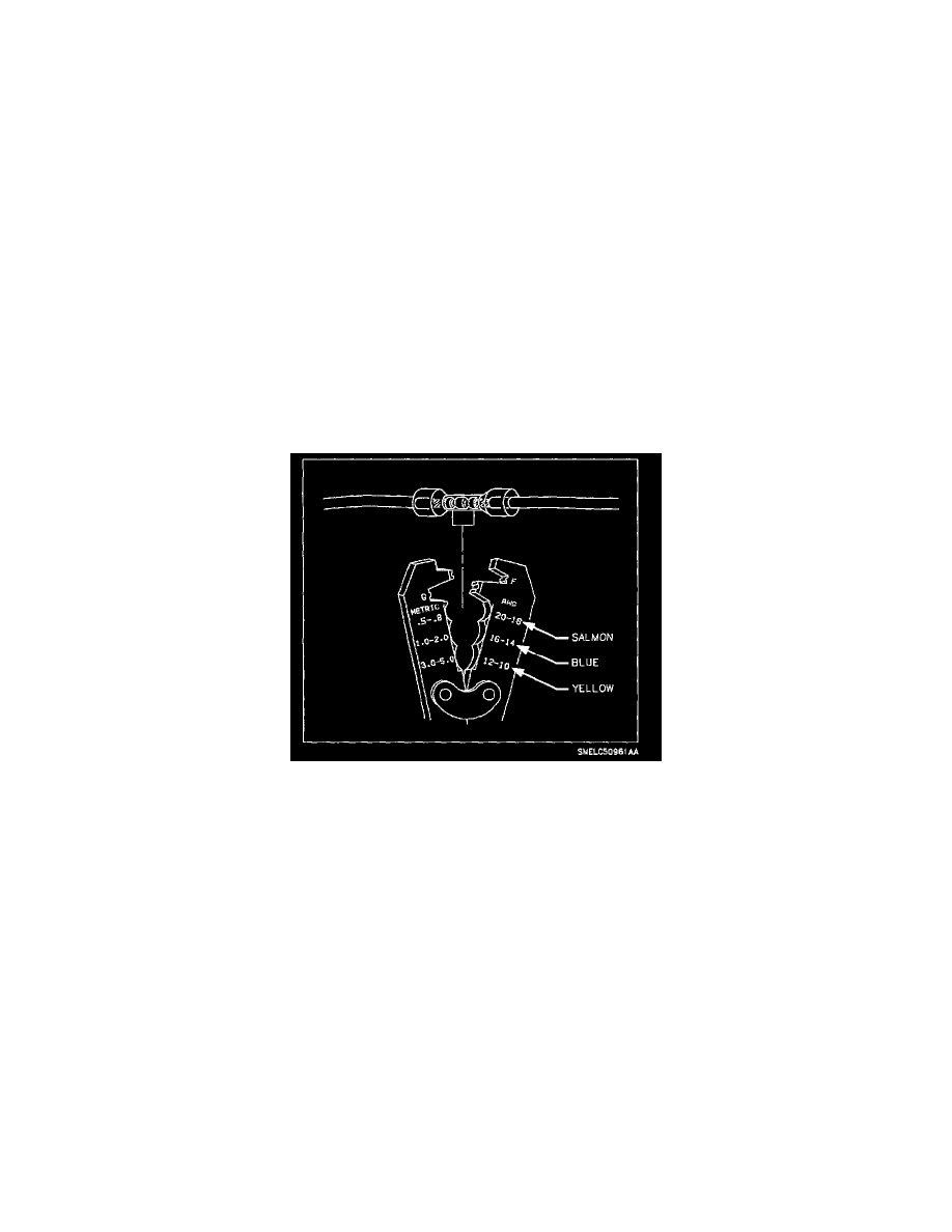
Splicing/Cut Lead Installation
With the low current and voltage wires in the Saturn vehicle, it is best to use approved Packard Electric Crimp and Seal Splice Sleeves (or equivalent).
1. Put connector seal (if equipped) on wire and strip approximately 9.5 mm (3/8 in.) of insulation off the wire.
2. Remove insulation from the end of the cut lead and the harness. Recommended strip length is 9.5 mm (3/8 in.). Caution must be used to prevent
cutting the wire strands.