
L200 L4-2.2L VIN F (2002)
number of different voltage scales. To determine what scale to use, always use the lowest scale on the multimeter that can be used to test the circuit. For
example, if the multimeter has a 200 millivolt scale, a 20 Volt scale and a 200 Volt scale, and you are testing for battery voltage (approximately 12-14
Volts), set the multimeter to the 20 Volt scale. If you should select a scale that is too low, the meter indicates this by displaying a 1 or an OL on the
display. This will not harm the multimeter, and you can always select a higher scale until a good reading is obtained. The same goes for selecting too
high of a scale. If you select the 200 Volt scale and you are testing for battery voltage (12.8 Volts), most multimeters will display 12 Volts. By selecting
the next smallest scale, 20 Volts, the multimeter's display will change to 12.8 volts.
Amperage (Current)
Since a multimeter has a very low resistance when measuring current, caution must be used to prevent damage to the multimeter. Always check the
recommendations, listed in the multimeter's owner guide for the maximum current to be tested for. As previously mentioned, most multimeters are
protected by a fuse when checking for current. However, not all multimeters are protected, and excessive current will damage a multimeter.
The most common use for measuring current in automotive applications is checking for parasitic current drain. This is the amount of current being drawn
by the vehicle with all electrical loads off. The normal parasitic current drain for a Saturn vehicle is less than 10 milliamps (although it can go as high as
14.1 milliamps if the vehicle has the Saturn approved anti-theft system installed). This current drain comes from components that require voltage to
sustain a memory circuit such as the clock, radio, powertrain control module, etc. However, when checking for parasitic current drain, always check to
see if the customer has installed any non-factory installed items that could require constant voltage such as a cellular phone, anti-theft system, etc.
IMPORTANT: The ignition key must be removed from the cylinder before parasitic load testing. The keyminder circuit is activated by the key cylinder
switch when the key is in the ignition cylinder, which adds 20 milliamps of current draw.
Continuity/Resistance/Diode
This group of settings on a multimeter allow you to accurately test for continuity and determine the resistance of many vehicle components.
Continuity
To check for continuity in a circuit use the lowest ohm scale available. Place the leads of the multimeter on each end of the circuit or component being
tested. A reading of less than one ohm indicates acceptable continuity.
Resistance
To test for resistance values, place the leads of the multimeter on each side of the circuit or component being tested. Adjust the ohm settings on the
multimeter until an acceptable reading is displayed. The lowest scale that gives a reading without going over the range (1 or OL) gives the most
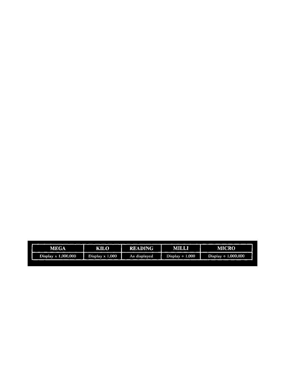
accurate reading. Compare the reading displayed on the multimeter to the specification found or bulletin. Verify that the scale reading on the
multimeter is the same as in the specification (megohms, kilohms or ohms).
NOTE: When using a multimeter on the ohmmeter or diode test scale, make sure the circuit or component is disconnected from a power source.
Applying voltage to a multimeter when you are measuring resistance can damage the multimeter.
Diode Testing
Most digital multimeters have a Diode setting. This setting is used to test a diode to verify current flows in only one direction.
A good diode will display between 0.4 and 0.8 volt on the meter when the leads are forward biasing the diode, this indicates the diode is allowing
current to flow in that direction. When the leads are reversed, the meter should read 1 or OL, indicating the diode is blocking the flow of current in the
opposite direction. This indicates a good diode. If the diode allows current flow in both directions or prevents current flow in both directions, the
diode is damaged and should be replaced.
Multimeter Display Reading
Connector Tester Adaptor
NOTE: Do not push multimeter probes into the connector terminals.