
L200 L4-2.2L VIN F (2002)
Splice Packs
IMPORTANT: Cavity references for slice packs on schematics may be different than the harness due to manufacturing constraints of the wire harness.
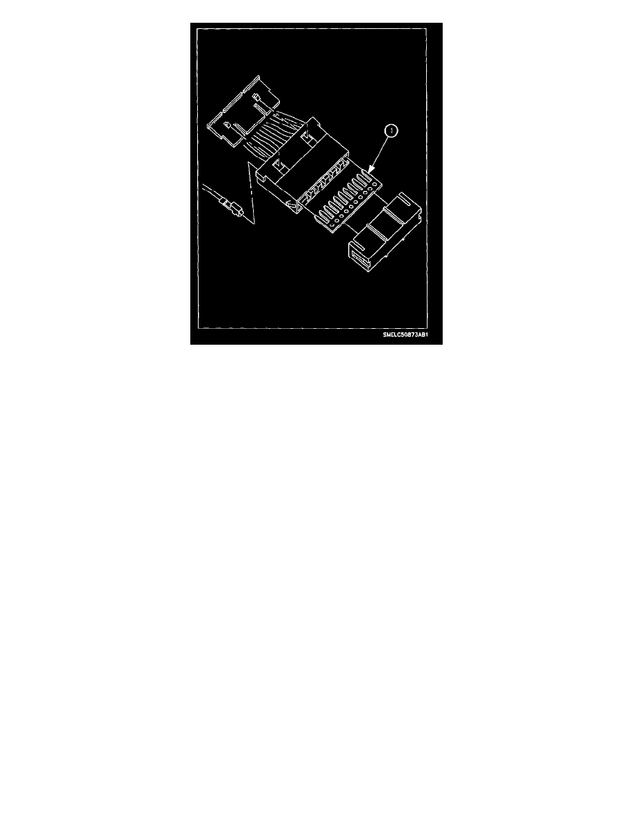
Splice packs are used to replace conventional soldering and clipped splices. The splice pack consists of a buss bar (1) with male blades that plug into a
standard female crimp on terminal. A plastic cover is placed over the buss bar to insulate it from surrounding wires and the environment. This feature
improves the reliability of splices.
Some of the grounding splice packs have an integral ring terminal as part of the buss bar. This way the splice pack can be directly connected to the
vehicle body instead of using a wire to go from the splice pack to a ring terminal.
Five - Step Trouble Shooting
1. Verify the complaint.
^
Perform System Performance Test, if section has one outlined.
^
Learn more about the nature and location of the problem. Use the general description to learn how the circuit operates, when the circuit should
operate, and how the components interact to make the circuit complete.
^
Analyze what parts of the system are working.
^
Do not fix only part of the problem.
^
Do not begin disassembly or testing until you have narrowed down the possible causes.
2. Analyze the electrical schematic and consult the flowcharts for the system being tested.
^
Look at the electrical schematic for the problem circuit. Determine how the circuit is supposed to work and look for minifuses, maxifuses,
circuit breakers, wires, and grounds that are shared with other systems or components. See if a shared wire is at fault by checking other
components fed by the wire. If several circuits fail at the same time, check for a common voltage or ground connection. If part of a circuit fails,
check the connections between the part that works and the part that does not work.
^
Follow the flowcharts to find the possible, cause(s) of the problem.
^
Based on the symptoms and your understanding of the circuit operation, identify one or more possible causes of the problem.
^
Refer to component location diagram for the system to help locate component and/or connector while diagnosing.
3. Isolate the problem by testing the circuit. Use diagnostic service probes as needed on 0.35, 0.50, and 0.80 2 mm (22, 20, and 18 gage) wires.
^
Perform circuit tests to check the diagnosis made in step two. You can either test for the most likely cause of failure first, or perform tests
which are most easily and quickly done.
^
Generally, fuses and grounds are easiest to check.
4. Fix the problem.
^
Once problem is identified, make repair.
^
Make sure to use the proper tools and safe methods mentioned in the "Vehicle Electrical Diagnostics".
5. Make sure the circuit works.
^
Operate all components in the repaired circuit in all modes of operation and verify that the repair has removed all symptoms.
^
Make sure no new problems have come up and that the original problem has been fixed.
Trouble Shooting Guides