
L200 L4-2.2L VIN F (2002)
Transmission Speed Sensor: Description and Operation
General Information
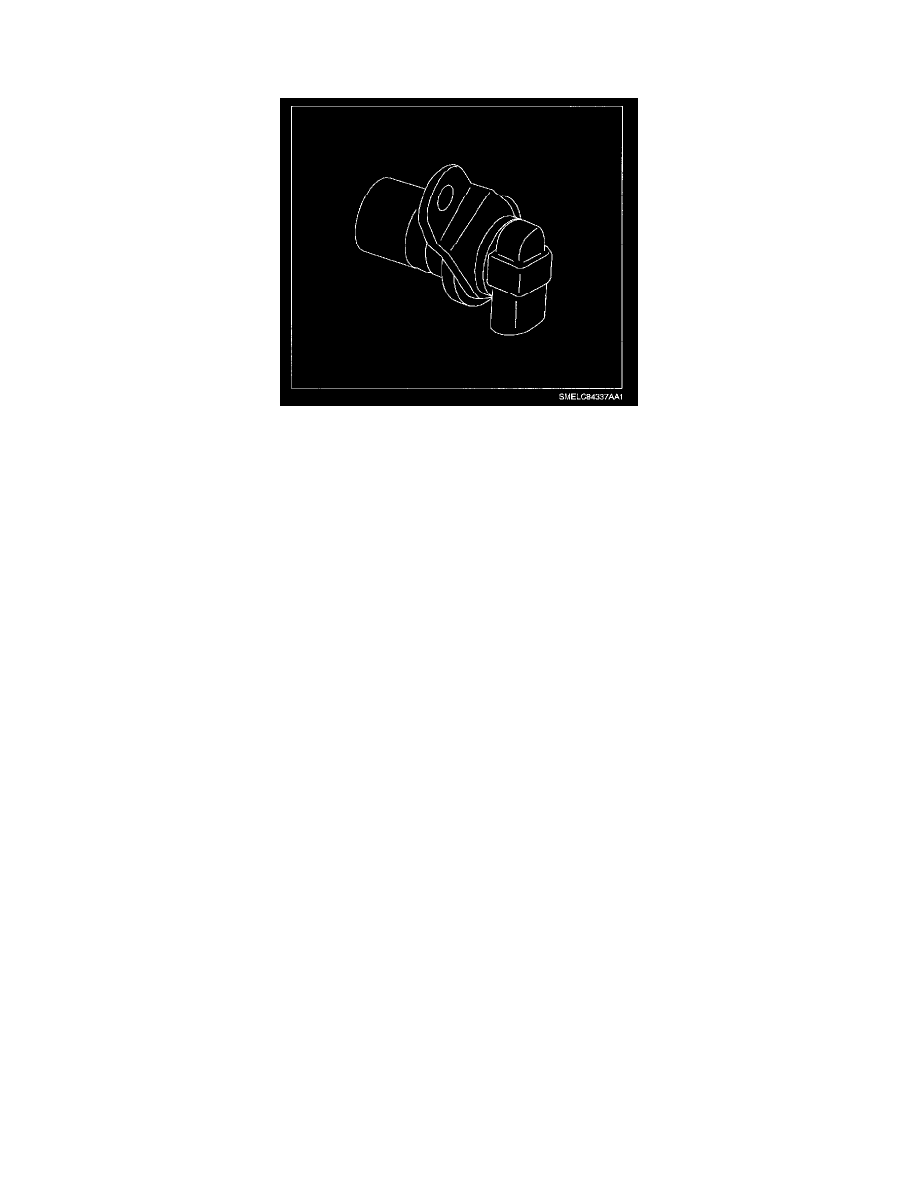
Output Speed Sensor (OSS)
The OSS is attached to the transaxle case near the right side inner CV joint. The sensor is used in conjunction with a sensor rotor pressed into the final
drive assembly. An air gap of 0.27-1.57 mm (0.011-0.062 in) exists between the sensor and rotor teeth. The OSS is a magnetic inductive pickup sensor,
which uses a permanent magnetic surrounded by a coil of wire. As the differential rotates, an AC voltage is induced in the OSS signal wires. The OSS
sensor produces this AC voltage of different amplitude (0.5 volts at 25 rpm to 200 volts at 1728 RPM) and frequency depending on the velocity of the
output shaft. The OSS produces the signal from the 16 evenly spaced notches on the sensor rotor. The OSS produces a readable AC voltage signal when
vehicle speed is above 5 km/h (3 mph). The OSS signal is sent to the PCM, which is used to determine the RPM of the output shaft. The output shaft
rpm is then used for many engine emission control calculations, idle speed adjustment, transaxle shift points, shift timing, TCC apply/release, transaxle
line pressure control, cruise control operation and I/P cluster speedometer readings.