
L300 V6-3.0L VIN R (2001)
Circuit Chart
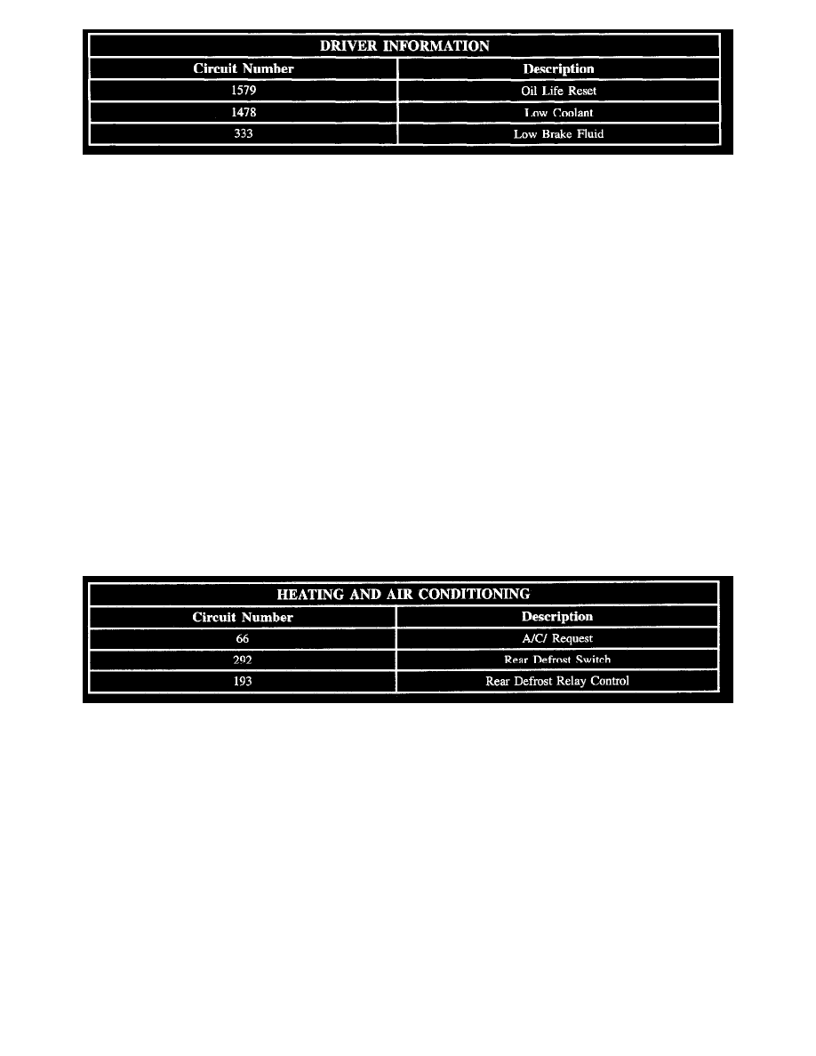
Circuit assignments for the Body Control Module (BCM) relating to driver information
ECU Malfunction
The BCM performs an Electrically Erasable Programmable Read-only Memory (EEPROM) checksum as a part of its internal diagnostics as the BCM is
operating. When the EEPROM checksum does not equal a predetermined value, DTC B1000 - ECU Malfunction sets. The checksum is the contents of
each memory location in EEPROM added together.
Electric Rear Defrost
When the rear defrost input circuit 292 to the BCM is momentarily switched to ground (as when the rear defrost switch is pressed), the BCM will
respond by grounding circuit 193, the coil of the rear defrost relay.
This action energizes the rear defrost relay providing power to circuit 293- rear defrost heater elements, circuit 683- heated mirror relay coil and circuit
683- rear defrost LED telltale. Momentarily switching circuit 292 to ground again will result in the BCM turning the rear defrost relay Off.
The first time in an ignition cycle that the rear defrost is activated, rear defrost will remain On for 15 minutes or until the ignition switch is turned OFF.
If rear defrost is activated again during the same ignition cycle, rear defrost will remain On for 7.5 minutes or until the ignition switch is turned Off.
Fuel Level
The BCM receives fuel level data from the ECM over CAN. The BCM calculates the data and sends the result to the cluster Class II to control the fuel
gauge deflection.
Grounding
Ground for the BCM is by circuit 550 through the I/P ground splice pack.
Heating And Air Conditioning Circuit Chart
Circuit Chart
Circuit assignments for the Body Control Module (BCM) relating to heating and air conditioning:
Horn
The BCM controls the operation of the horns for the security system and Remote Keyless Entry (RKE) functions. Circuit 28 is grounded by the BCM
when horn operation is desired. Normal operation of the horn is performed by the horn switch grounding the horn relay and is not controlled by the
BCM.
There is a 30 second delay prior to setting DTC 2752 - Horn Relay Coil Circuit Low for grounded circuit conditions. It is possible to set DTC 2752 if
the horn is operated by the horn switch for greater than 30 seconds
Instrument Panel Gauges
The instrument panel gauges are controlled by the Body Control Module (BCM) via the serial data link to the Instrument Panel Cluster (IPC).