L300 V6-3.0L VIN R (2001)

8.
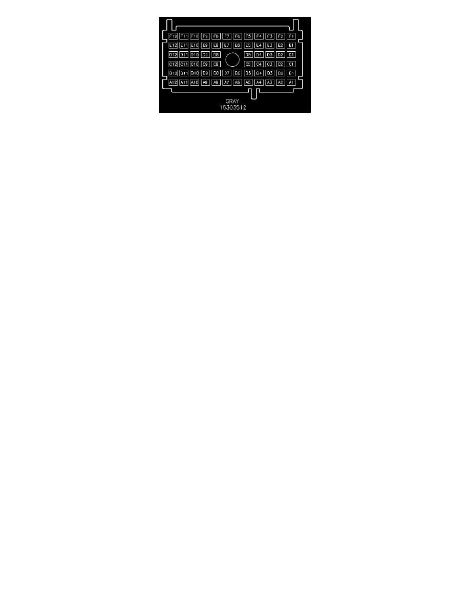
Disconnect gray 68-way connector.
9.
Locate RED 5.0 mm (10 gage) wire (circuit 502) at pin A11 and cut 76 mm (3 inches) from connector.
10.
Using two of the wires in the splice connector, butt connect the two cut ends of the RED 5.0 mm (10 gage) (circuit 502) to the splice connector
using yellow splice sleeves.
11.
Reconnect gray 68-way connector.
12.
Route 3rd wire in splice pack connector toward center of the console under the dash.
13.
Remove radio bezel and radio.
14.
Route relay (P/N 22688666) wire located at pin 87 at the relay through radio opening toward LIPFB.
15.
Butt connect wire from pin 87 at the relay to the 3rd wire from the splice connector routed from the LIPFB using a yellow splice sleeve.
16.
Remove left side console extension.
17.
Install after blow module (P/N 22679784) under the HVAC module.
18.
Locate WHT wire (pin E) at the after blow module pig tail.
18.1. Route WHT wire (pin E) through the front of dash pass through for the I/P harness to the underhood junction fuse block.
18.2. Remove top of junction block to gain access to the wires in the black 68-way connector.
18.3. Route WHT wire (pin E) into lower cavity of the UHFB.
18.4. Locate circuit 459 at pin C4 in the black 68-way connector at the UHFB.
18.5. Splice WHT wire into circuit 459 a few inches from the 68-way connector using a salmon splice sleeve.
18.6. Install top of junction block into base.
18.7. Using electrical tape or wire ties, secure white wire to the wiring harness.
19.
Route remaining wires from the after blow module up into the radio cavity in the I/P.
20.
Butt connect the BLK/ORN wire (pin G) from the after blow module to the relay wire from pin 85 using a salmon splice sleeve.
21.
Make the following splices at the Radio gray 24-way connector.
21.1. Splice the ORN wire from pin A at the after blow module into ORN .5 mm (20 gage) wire (circuit 440) in cavity B1 using a salmon splice
sleeve.
21.2. For 2001-2003 model year vehicles: splice the RED wire from pin B at the after blow module into YEL .35 mm (22 gage) wire (circuit 43)
in cavity B2, using a salmon splice sleeve.
For 2004 model year vehicles: splice the RED wire from pin B at the after blow module into YEL .35 mm (22 gage) wire (circuit 43) in cavity B11
using a salmon splice sleeve.
21.3. Splice the BLK/WHT wire from pin C at the after blow module into BLK 1.0 mm (16 gage) wire (circuit 550, ground) in cavity A12 using a
blue splice sleeve.
