
LW2 V6-3.0L VIN R (2000)
Circuit assignments for the Body Control Module (BCM) relating to gearshift:
GEARSHIFT UNLOCK
The gearshift unlock solenoid is energized by the BCM switching circuit 816 to ground. When energized, the gearshift unlock solenoid will allow
shifting from PARK. A condition for shifting from PARK is that the foot brake must be applied. The BCM receives this information over the serial
data link from the engine controller.
The BCM also monitors ignition 1 circuit 339 and ignition 2 circuit 743 to determine if the ignition switch is in the RUN or ACC position.
General Description
Circuit Chart
CIRCUIT CHART
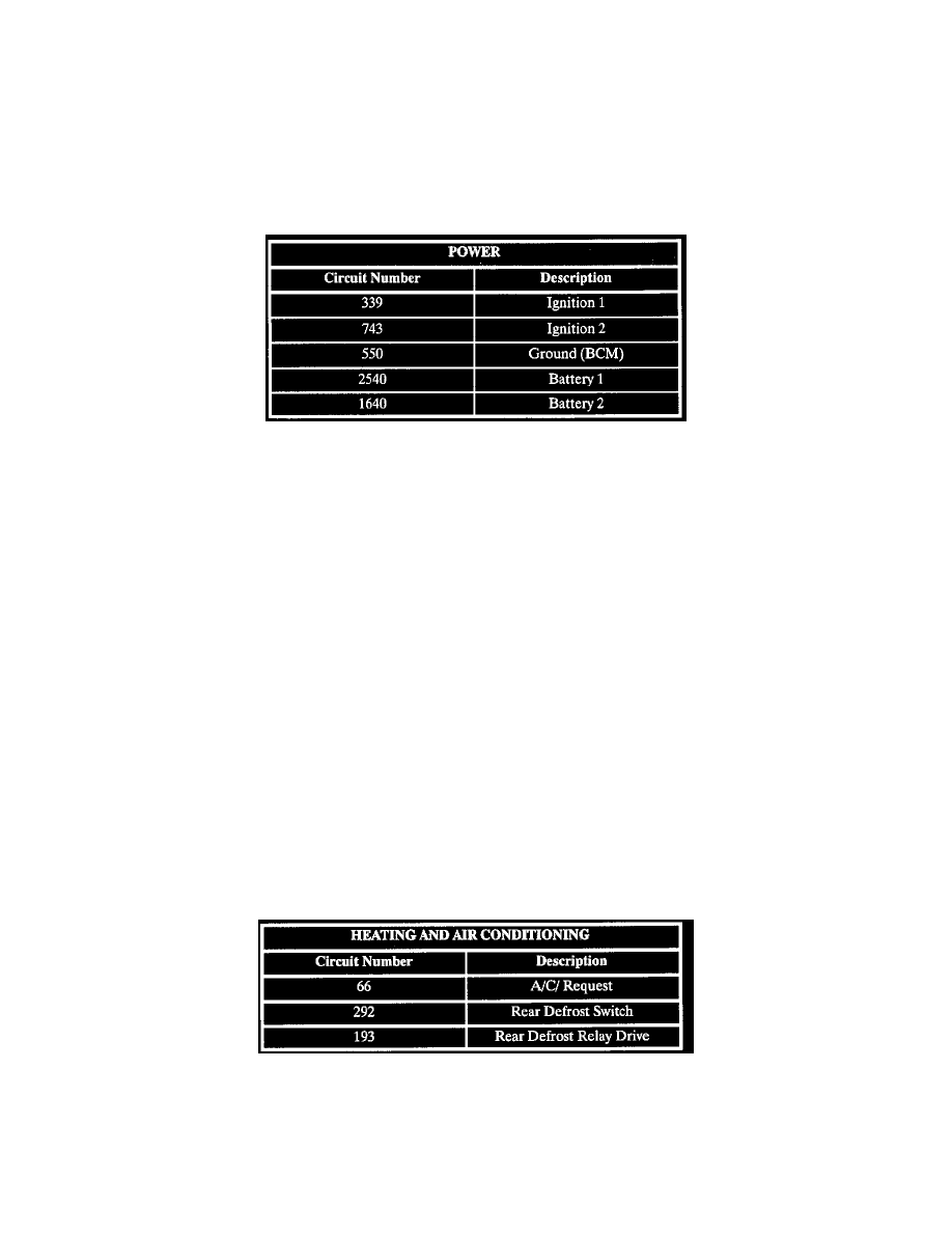
Circuit assignments for the Body Control Module (BCM) relating to device power:
DEVICE POWER
Battery voltage is supplied to the BCM by circuit 2540. This input is internally monitored by the BCM for proper operating voltage. The proper
operating voltage range is from 9 to 16 volts.
GROUNDING
Ground for the BCM is by circuit 550 through the left instrument panel junction block and right body ground splice pack/body ground.
POWER MODE
The BCM monitors ignition 1 voltage circuit 339, ignition 2 voltage circuit 743 and the Engine Run Flag (ERF). The ERF is a serial data message
from the engine controller. The BCM determines the state of the ignition switch for all modules on the serial data link.
ECU MALFUNCTION
The BCM performs an Electrically Erasable Programmable Read-Only Memory (EEPROM) checksum as a part of its internal diagnostics as the
BCM is operating. When the EEPROM checksum does not equal a predetermined value, DTC B1000 - ECU Malfunction sets. The checksum is the
contents of each memory location in EEPROM added together.
OPTION CONFIGURATION
The vehicle option content information must be entered as part of the BCM programming procedure. If the vehicle option content information is not
included and programming procedure is completed, DTC B1000 - Option Configuration Error will set.
Heating And Air Conditioning
Circuit Chart
CIRCUIT CHART
Circuit assignments for the body control module (BCM) relating to heating and air conditioning:
ELECTRIC REAR DEFROST
When the rear defrost input circuit 292 to the BCM is momentarily switched to ground (as when the rear defrost switch is pressed), the BCM will