
LW2 V6-3.0L VIN R (2000)
11.3 Using a yellow splice sleeve, splice the other half of the ORN 5.0 mm (10 gage) wire from HVAC inline connector that goes to the I/P body
harness into BLK/ORN .5 mm (20 gage) wire (Pin G) from delayed blower control module.
11.4 At terminal H, using a salmon (pink) splice sleeve, splice BRN .35 mm (22 gage) wire from HVAC inline connector into RED .50 mm (20
gage) wire from delayed blower control module.
12.
Make the following splices at the Radio gray 24 way connector:
12.1 At terminal B3, using a salmon (pink) splice sleeve, splice ORN .50 mm (20 gage) wire from Radio 24 way connector into ORN .50 mm (20
gage) (Pin A) wire from delayed blower control module.
12.2 At terminal A12, using a blue splice sleeve, splice BLK 1.0 mm (16 gage) wire from Radio 24-way connector into BLK/WHT .50 mm (20
gage) (Pin C) wire from delayed blower control module.
13.
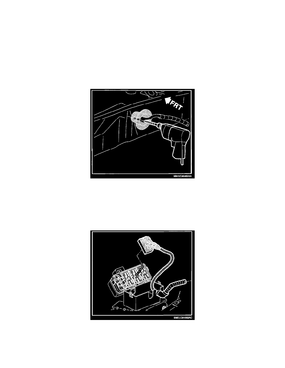
From inside the vehicle, carefully drill a hole through left side (ten o'clock position) of engine harness grommet, using a 2.0 mm drill bit.
14.
Locate WHT wire (pin E), from delayed blower module and tape the wire onto the end of an awl and push through drilled hole in grommet. From
engine compartment untape WHT wire from awl and pull wire all the way through.
15.
Remove battery shield.
16.
Unsnap engine coolant reservoir line from the fuse block cover.
17.
Open UHFB and disconnect the UHFB black 68-way connector (L61) or gray 68-way connector (L81) and then:
17.1 Locate and remove terminal C4 (L61) GRN/WHT wire or A7 (L81) BLK/WHT wire from the black (L61) or gray (L81) UHFB 68-way
connector.
17.2 Cut off terminal end from the GRN/WHT wire or BLK/WHT wire.