
LW2 V6-3.0L VIN R (2000)
IMPORTANT:
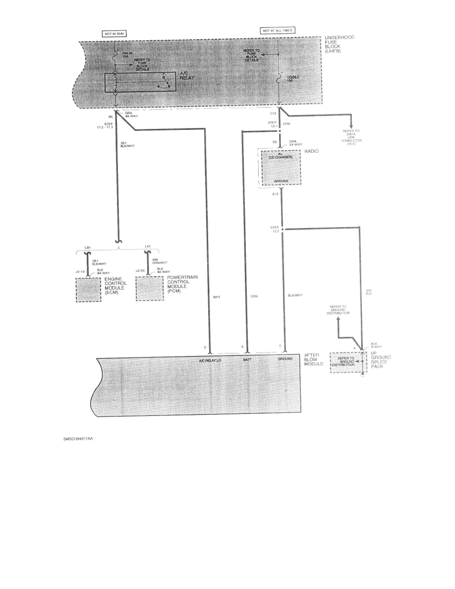
For steps 11 though 15, refer to the electrical schematic shown.
IMPORTANT:
For information on splicing wires, refer to "Wiring Splicing" instructions in this bulletin.
11.
Make the following splices at the HVAC inline BLK 12-way connector.
11.1 At Pin A, cut orange wire (circuit 52), 76 mm (3 in.) from connector on the side going to the HVAC control head, then:
11.2 Using a yellow splice sleeve, splice the ORN 5.0 mm (10 gage) wire that goes to the HVAC control head into TAN/ORN .5 mm (20 gage)
wire (Pin F) from delayed blower control module.