
LW2 V6-3.0L VIN R (2000)
Circuit Chart
CIRCUIT CHART
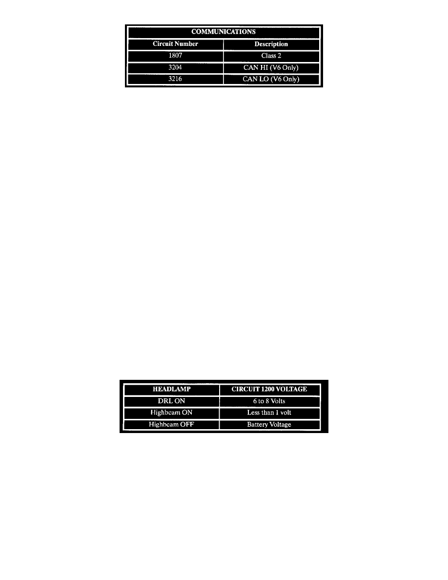
Circuit assignments for the body control module (BCM) relating to communications:
CLASS 2 COMMUNICATIONS
The class 2 serial data circuit 1807 is used to communicate information between modules (for example the body control module and the engine
controller).
Contained in each module's memory is a list of serial data messages that are important and should be received by the module. Also contained are the
default actions to be taken by the module, if one of the important messages is not received in time. One of those important messages is the State Of
Health (SOH) message. This message is sent by a module (if no other message needs to be sent) to let all the other modules on the serial data circuit
know the sending module is working correctly.
Each time the ignition is turned ON, all the modules on the class 2 serial data circuit first learn the other modules connected to the class 2 serial data
circuit. Modules are able to learn the other modules on the serial data circuit because each of the important messages has a source identifier as part of
the message.
This process of learning by a module allows the module to know if it has lost communication with a specific module on the class 2 data circuit.
CAN COMMUNICATIONS (V-6 ONLY)
The Engine Control Module (ECM) and the Transmission Control Module (TCM) communicate with each other over the CAN (controller area
network) bus circuit 2501 and circuit 2500. The CAN bus is a communication link similar to class 2.
The Body Control Module (BCM) acts as the interpreter or gateway between the other modules connected to the class 2 serial data circuit 1807 and
the ECM and TCM connected to the CAN bus circuit 2501 and circuit 2500.
State of health (SOH) messages are sent from the ECM and TCM to the BCM when the ignition is turned ON and during vehicle operation. These
messages tell the BCM the ECM and TCM are working correctly. The BCM has an internal reset counter to monitor the status of the CAN bus. When
the counter reaches a defined value and no CAN messages have been received from either the ECM or TCM, the BCM sets DTC U2104 - CAN Bus
Reset Counter Overrun.
Daytime Running Lamps
Daytime Running Lamps
Daytime Running Lamps (DRL) are controlled by the BCM based on input from the high beam headlamp circuit 1200, the low beam headlamp circuit
1201, the parking brake circuit 1134 and ignition switch state.
When DRL operation is desired, the BCM switches circuit 592 to ground. This action energizes the DRL relay. When energized, the DRL relay operates
the left high beam headlamp and right high beam headlamp as a series circuit (one - half of battery voltage across each high beam headlamp).
When DRL operation is not desired, the BCM does not provide ground for the DRL relay. When not energized (as when high beam headlamps are
desired) the DRL relay operates the right and left high beam headlamps as a parallel circuit (full battery voltage across each high beam headlamp).
For DRL operation, the parking brake must be fully released, the ignition switch must be in the RUN position and headlamp switch must be in the Off
position. Under normal operating conditions, the feedback voltage to the BCM measured at circuit 1200 is: