
LW2 V6-3.0L VIN R (2000)
Schematic (Part 2 Of 3)
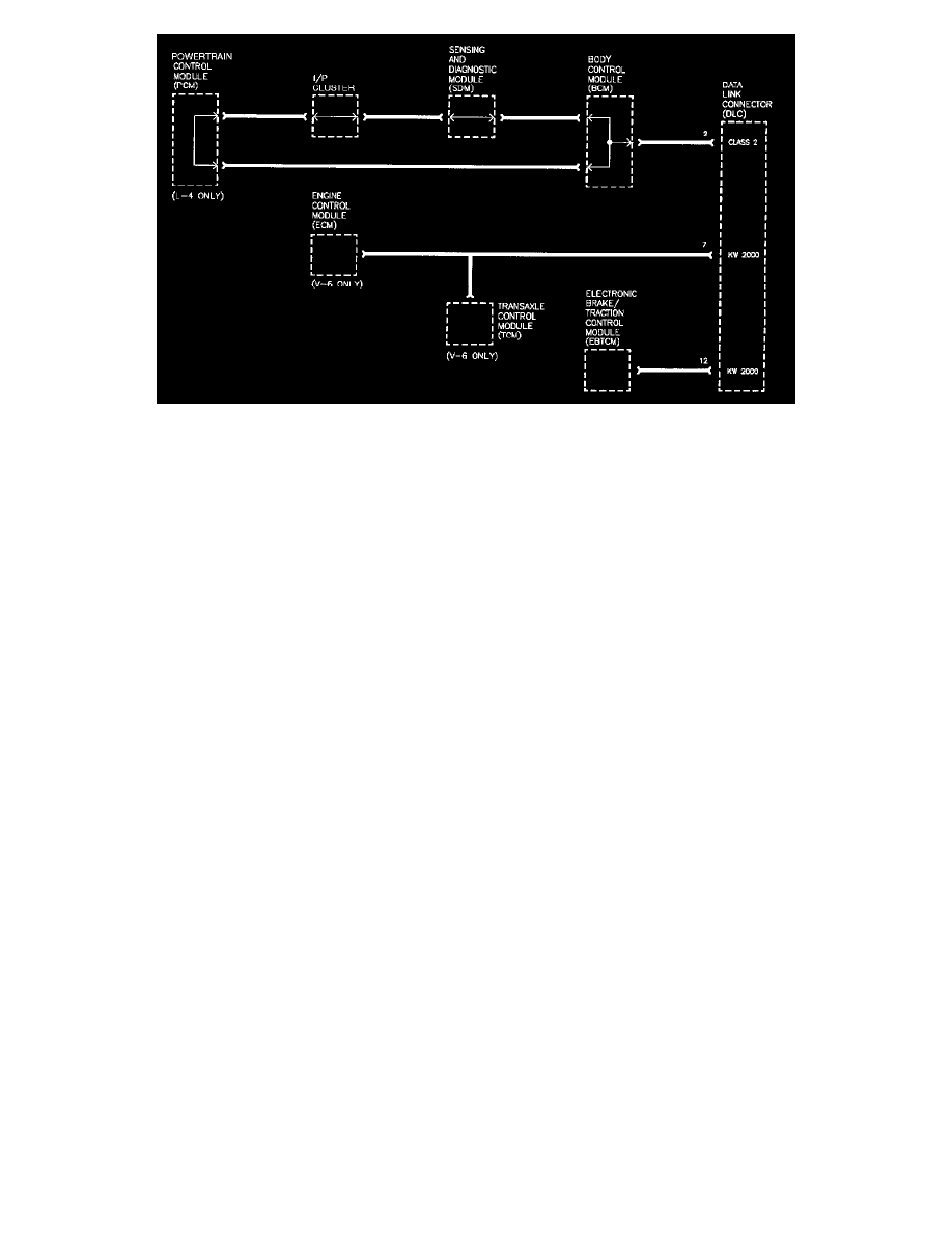
Since the BCM is the master on the Class II link and the SDM is on every vehicle, these controllers should be communicated with first since they may
help to determine potential serial data link errors.
This chart continues establishing communications with each of the applicable modules on the vehicle.
The 4 cylinder (L61) the engine and transaxle are controlled by a powertrain control module which communicates on the Class II link. The V6 (L81)
engine and automatic transaxle communicates with the Scan tool over a KW2000 data link. Also, the electronic brake/traction control module (EBTCM)
communicates over a KW2000 data link, but on a separate wire.
If communications can be established with each control module, and there are no DTCs associated with any module, the on-board diagnostics system
check is complete. If no DTCs are detected, the next step is refering to the symptom section related to the customer complaint.
Chart 3