
RELAY AWD V6-3.9L (2007)
6. If the brake rotor assembled LRO measurement exceeds the specification, bring the LRO to within specifications. Refer to Brake Rotor Assembled
Lateral Runout Correction. See: Testing and Inspection/Brake Rotor Assembled Lateral Runout Correction
7. Install the brake caliper and the brake caliper bracket as an assembly to the suspension knuckle.
8. Install the tire and wheel assembly.
9. Lower the vehicle.
10. If the brake rotor was refinished or replaced, or if new brake pads were installed, burnish the pads and rotors. Refer to Brake Pad and Rotor
Burnishing.
Rear Brake Rotor Replacement (J65, JL9)
Rear Brake Rotor Replacement (J65, JL9)
Tools Required
*
J 41013 Rotor Resurfacing Kit
*
J 42450-A Wheel Hub Resurfacing Kit
Caution: Refer to Brake Dust Caution.
Removal Procedure
1. Raise and support the vehicle. Refer to Vehicle Lifting.
2. Remove the tire and wheel assembly.
Notice: Support the brake caliper with heavy mechanic wire, or equivalent, whenever it is separated from its mount and the hydraulic
flexible brake hose is still connected. Failure to support the caliper in this manner will cause the flexible brake hose to bear the weight of
the caliper, which may cause damage to the brake hose and in turn may cause a brake fluid leak.
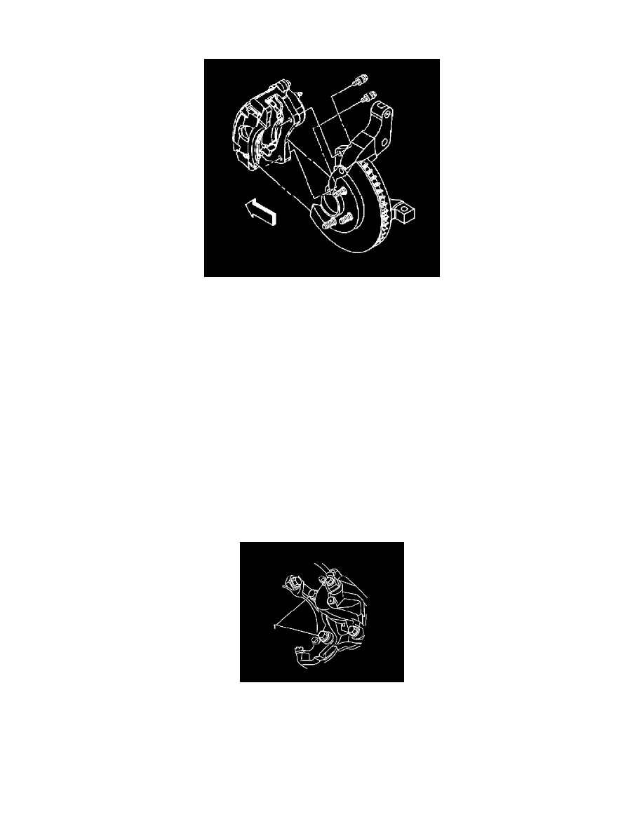
3. Remove the caliper bracket bolts (1).
4. Remove the brake caliper and the caliper mounting bracket as an assembly from the suspension knuckle and support the assembly with heavy
mechanic's wire, or equivalent. Ensure that there is no tension on the hydraulic brake flexible hose.
5. Matchmark the position of the brake rotor to the wheel studs.
6. Remove the brake rotor. If the rotor is difficult to remove, ease it off by gently rotating it as you pull outward.