
RELAY FWD V6-3.9L VIN 1 (2006)
5. Insert the J 42019 (12122378) into the 2 cavities on each side of the terminal at the front of the connector and push until you feel the tool
disengage the terminal retainers.
6. Carefully pull the terminal out of the connector. Always remember never use force when pulling a terminal out of a connector. If the terminal is
difficult to remove, repeat the entire procedure.
TERMINAL REPAIR PROCEDURE
Use the appropriate wire assembly repair kits available through Saturn Service Parts.
Connector Position Assurance Locks
CONNECTOR POSITION ASSURANCE LOCKS
The connector position assurance (CPA) is a small plastic insert that fits through the locking tabs of the connector. CPAs are used in various connectors
throughout the vehicle. CPAs are also used in all SIR system electrical connectors. The CPA ensures that the connector halves cannot vibrate apart. You
must have the CPA in place in order to ensure good contact between the mating terminals, of the connector.
Delphi Connectors (Micro .64)
DELPHI CONNECTORS (MICRO.64 CONNECTORS)
TOOLS REQUIRED
J-38125 Terminal Repair Kit
IMPORTANT: When probing female 0.64 terminals, it is important to use the correct adapter. There have been some revisions to the test adapter for
0.64 terminals. The proper adapter for 0.64 terminals is the J 35616-64B which has a tin terminal and a blue wire between the base and tip. Failure to
use the proper test adapter may result in damage to the terminal being tested and improper diagnosis.
TERMINAL REMOVAL PROCEDURE
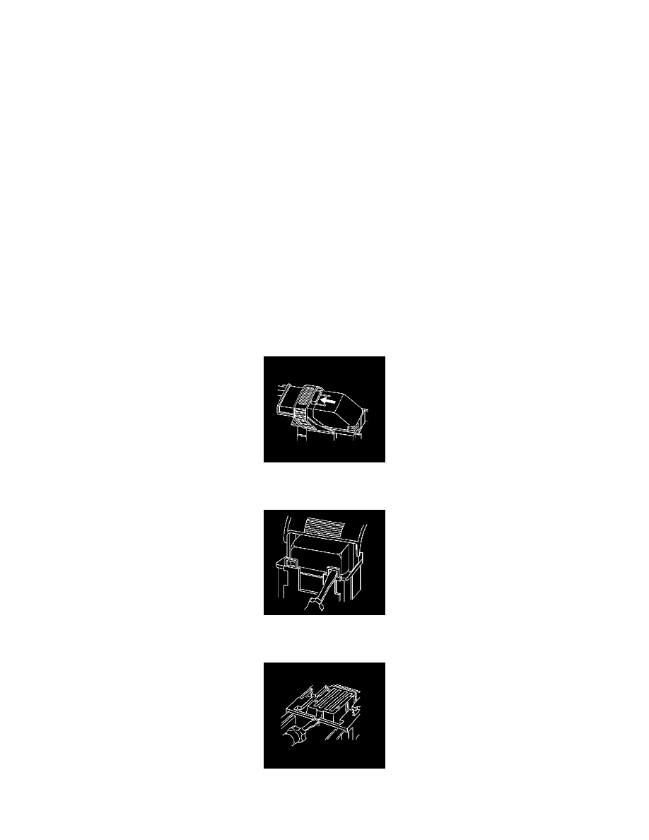
1. Locate the lever lock on the wire dress cover. While pressing the lock, pull the lever over and past the lock.
2. Disconnect the connector from the component.
3. Locate the 2-wire dress cover locking tabs that are opposite the wire end of the connector. Use a small flat-bladed tool to unlock the dress cover.
4. Once the front 2 locks are unlocked, lift the back 2 locks that are on the wire side of the connector.
5. If the connector has a nose piece, use a small flat-bladed tool to remove the nose piece by inserting the blade into the slot on the front of the
connector and prying up on the nose piece.The nose piece covers the terminal release holes on a specific Micro 64 connector. Not all Micro 64