
SC L4-1.9L DOHC VIN 7 (1991)
u.
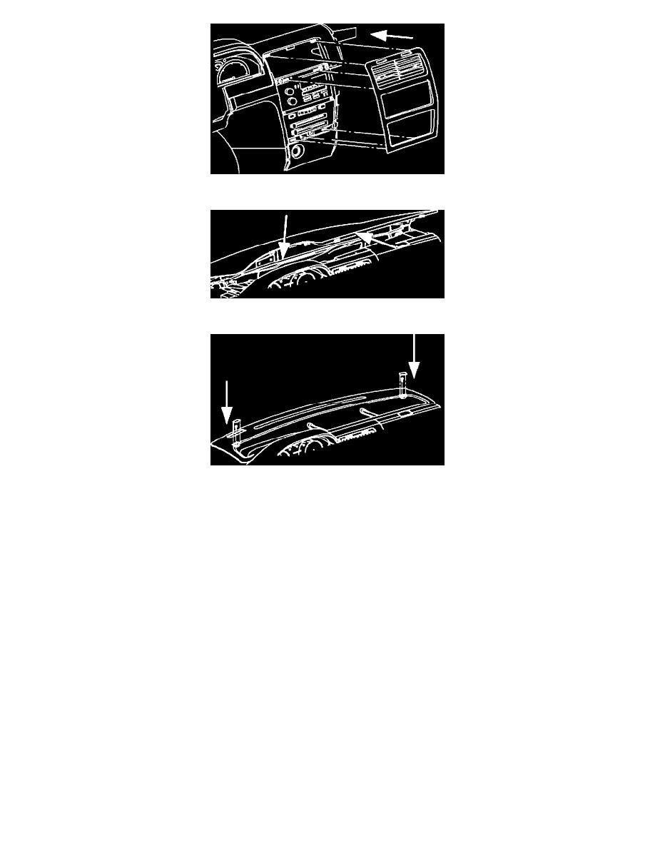
Install center air outlet/trim panel, by pushing in at clip locations.
v.
Install upper trim panel by inserting it into clips at windshield and snapping rear of panel into place.
w.
Install upper trim panel screws and screw caps.
x.
Connect negative battery terminal.
y.
Set clock to proper time.
10. Remove jumper pigtails and connect the electrical connectors to both sensors. Install air cleaner duct assembly and verify that the
electrical connector to the engine induction air temperature sensor is connected. Clear PCM codes set during testing procedures.
11. Start the engine and monitor the coolant temperature gage. Run the engine until the engine cooling fan turns on. Verify that the
temperature gage readings compare with Figure 1, and that the customer concern is eliminated.
Parts Requirements:
Model
Codes
Usage
21020124
Engine Coolant
-
LLO & LKO
Temperature Indicator
Sensor Assembly
Replacement
21020104
Coolant Temperature
-
LLO & LKO
Indicator-PCM Sensor
Assembly
21021209
Cluster Asm - Inst
B69
LKO & MP2
& J41