
Sky L4-2.0L Turbo (2008)
Heated Glass Element: Testing and Inspection
Rear Window Defogger Malfunction
Diagnostic Instructions
*
Perform the Diagnostic System Check - Vehicle (See: Testing and Inspection/Initial Inspection and Diagnostic Overview/Diagnostic System
Check - Vehicle) prior to using this diagnostic procedure.
*
Review Strategy Based Diagnosis (See: Testing and Inspection/Initial Inspection and Diagnostic Overview/Strategy Based Diagnosis) for an
overview of the diagnostic approach.
*
Diagnostic Procedure Instructions (See: Testing and Inspection/Initial Inspection and Diagnostic Overview/Diagnostic Procedure Instructions)
provides an overview of each diagnostic category.
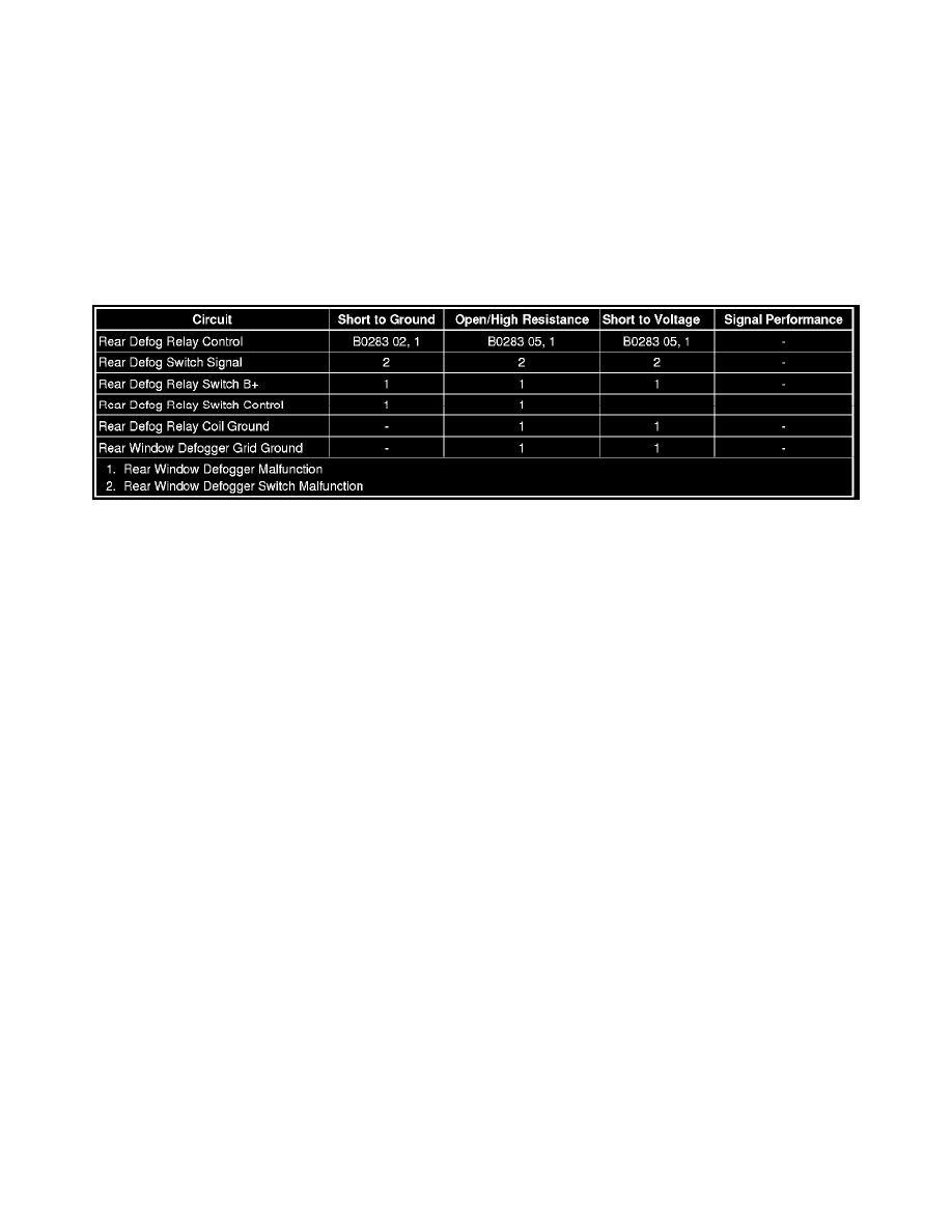
Diagnostic Fault Information
Circuit/System Description
The body control module (BCM) controls the rear window defog relay located in the underhood fuse block. The rear window defog switch located on the
HVAC control module is hard wired to the BCM. The rear window defog switch provides the request signal to the BCM. With the ignition switch in the
RUN position, the BCM supplies voltage to the rear window defog switch via the rear defog switch signal circuit. When the rear window defog switch is
pressed, the switch contacts close and ground is supplied. The BCM interprets the flow of voltage as a request to turn the rear defogger ON. The BCM
energizes the rear window defog relay by applying voltage to the relay coil via the rear defog relay control circuit. When the rear window defog relay
coil is energized, the switch contacts of the rear window defog relay close allowing battery voltage to flow from the REAR DEFOG fuse through the
closed switch contacts and out the relay switched output to the rear window defogger grid. Ground for the rear window defogger grid is provided at
G301. The BCM also illuminates the rear defog indicator LED located on the HVAC control module with the supplied voltage from the rear defog relay
control circuit.
Reference Information
Schematic Reference
Defogger Schematics (See: Diagrams/Electrical Diagrams)
Connector End View Reference
Component Connector End Views (See: Diagrams/Connector Views)
Description and Operation
Rear Window Defogger Description and Operation (See: Windows/Description and Operation/Rear Window Defogger Description and Operation)
Electrical Information Reference
*
Circuit Testing (See: Testing and Inspection/Component Tests and General Diagnostics)
*
Connector Repairs (See: Testing and Inspection/Component Tests and General Diagnostics)
*
Testing for Intermittent Conditions and Poor Connections (See: Testing and Inspection/Component Tests and General Diagnostics)
*
Wiring Repairs (See: Testing and Inspection/Component Tests and General Diagnostics)
Scan Tool Reference
Control Module References (See: Testing and Inspection/Programming and Relearning)
Circuit/System Verification
1. Ignition ON, observe the scan tool rear defog switch parameter while pressing the rear window defogger switch. The reading should change
between ON and OFF.