
SL L4-1.9L SOHC VIN 8 (1997)
INSTALLATION
1. Position brake control assembly onto brake booster studs and install fastening nuts.
^
Torque: 27 Nm (20 ft.lbs.)
CAUTION: Be careful not to bend brake lines.
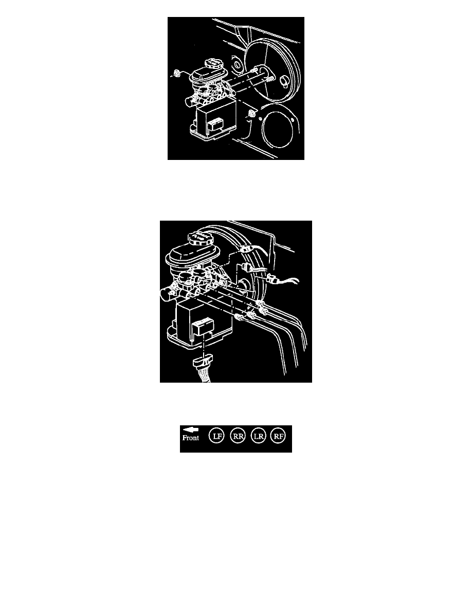
Fig. 63 Removing Anti-lock Brake Control & Master Cylinder Assembly
2. Position brake lines into the brake control assembly and secure brake line fitting nuts.
^
Torque to 32 Nm (24 ft. lbs.)
3. Install the six-pin electrical connector onto motor pack assembly.
4. Check to be sure that connector is fully seated and install CPA retainer.
5. Install electrical connector onto brake fluid level sensor switch.
6. Install two electrical connectors onto solenoid valves.
NOTE: Check to be sure that all electrical connectors are fully seated and latches are engaged.