
SL L4-1.9L SOHC VIN 8 (1997)
Hydraulic Control Assembly - Antilock Brakes: Service and Repair
CAUTION: Do not attempt to disassemble the solenoid; it is serviceable only as an assembly.
NOTE: The lip seal is not installed in a groove and is free to slide on and off the solenoid. The lip seal may slide off the solenoid and stay in the
modulator bore during solenoid removal. Make sure to remove seal from modulator bore if this occurs.
REMOVAL
1. Clean dirt from solenoid valve and area around solenoid.
2. Remove electrical connector from solenoid valve.
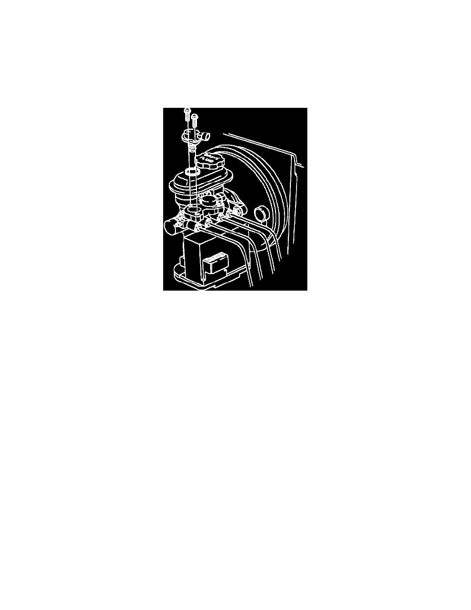
Fig. 62 Anti-lock Brake Solenoid Valve Removal
3. Remove two solenoid-to-modulator T0RX(r) head screws and remove solenoid valve from modulator.
CAUTION: Second design solenoid uses a lip seal at lower seal location. Be sure that seal is installed on solenoid correctly with lip or cupped side of
seal facing up toward top of solenoid.
INSTALLATION
1. Lubricate solenoid valve lip seal and/or 0-rings with clean brake fluid and install on solenoid valve.
2. Position solenoid valve into modulator. Push solenoid valve into the modulator until solenoid flange is fully seated.
CAUTION: Be sure solenoid electrical connector faces in correct direction.
3. Install two solenoid-to-modulator T0RX head screws.
^
Torque to 5 Nm (45 inch lbs.)
4. Install electrical connector onto solenoid valve.
5. Fill brake fluid reservoir with clean brake fluid up to the base of the reservoir filler neck.
6. Bleed brake system. See: Service and Repair