
SL L4-1.9L SOHC VIN 9 (1991)
Crankshaft Position Sensor: Description and Operation
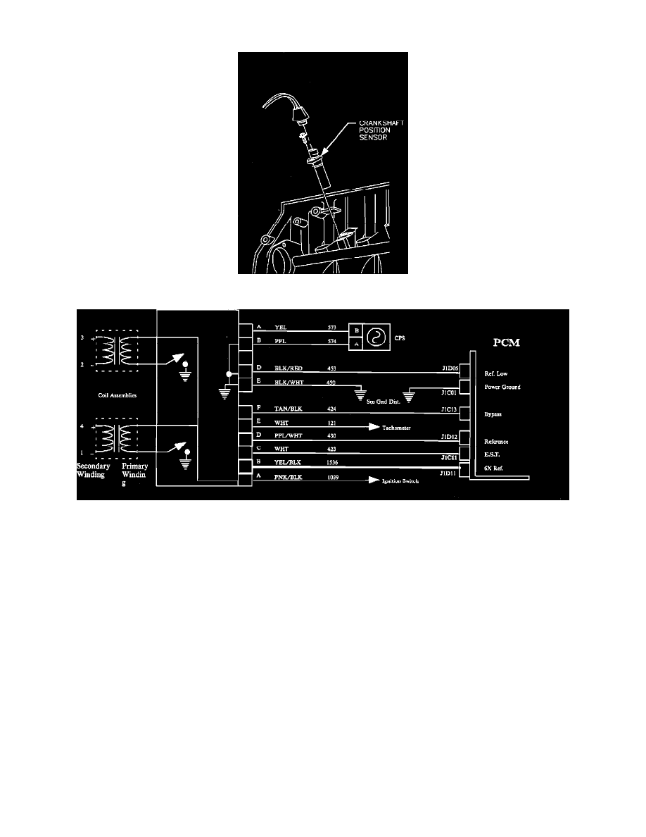
Crankshaft Position Sensor.
Ignition System Wiring.
PURPOSE
The electronic module accepts ignition timing information from the PCM and engine position information from a crankshaft position sensor
(CPS). It charges up the appropriate ignition coil to a preset current limit then turns "OFF" the primary current at the desired engine position to
create a high voltage signal that is routed to the spark plug to ignite the air/fuel mixture.
The crankshaft sensor signal is transferred to the PCM for other uses. The PCM uses this signal to control the fuel injection timing.
ENGINE POSITION
The CPS signal defines engine position. A CPS pulse occurs at each TDC, at 60 degrees after top dead center, (ATDC) and at 120 degrees ATDC.
A seventh pulse, referred to as sync pulse, occurs at 70 degrees ATDC of cylinder # 1.
INTERPRETATION OF CRANK SIGNAL
Crankshaft rotation initiates CPS pulses. With B+ applied to the DIS module, any valid CPS pulses shall initiate reference pulses. The BYPASS
line is held low by the PCM. The system is in BYPASS mode. The REF signal and the 6X signal begin switching upon recognition of the first CPS
pulse. The EST is held low by the DIS module. Spark firing events begin at TDC of the first cylinder following a recognized sync pulse. The
TACH signal begins switching with the first spark firing event.
Crankshaft Position Sensor-Positive I
The crankshaft position sensor (CPS) positive line is tied to the positive connection of the polarized variable reluctance crankshaft position sensor.
The peak positive voltage depends on engine rpm, and ranges from 300 millivolts to 125 volts.