
SL L4-1.9L SOHC VIN 9 (1991)
Transmission Position Switch/Sensor: Description and Operation
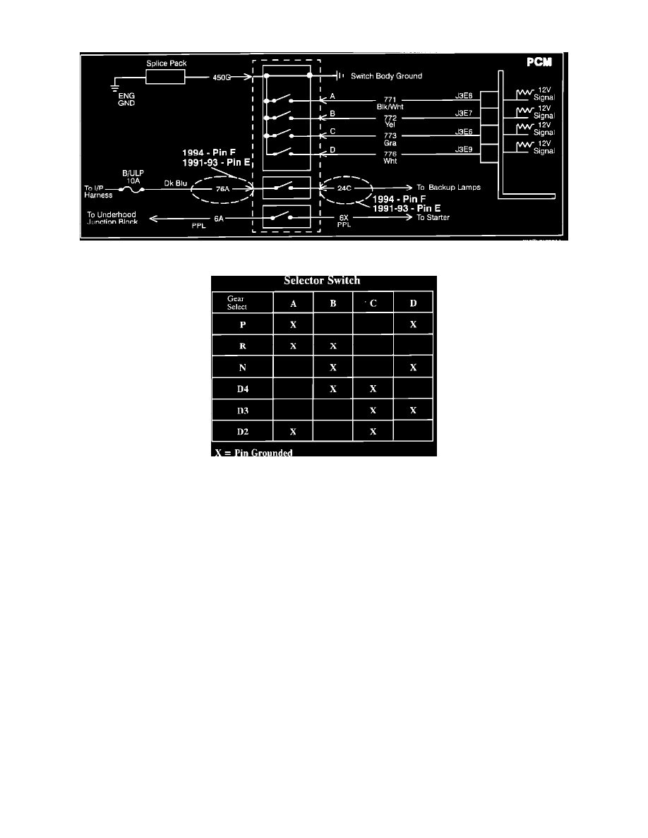
Wiring Diagram
Selector Chart
PURPOSE
The transaxle controller, located inside the powertrain control module (PCM) receives five signals from various switches and signals and two
signals (vehicle speed and engine rpm), internally from the engine control module, also located within the PCM. The PCM uses this information
during control of the transaxle shift points.
OPERATION
The transaxle gear selector switch contains four switches that ground four different circuits. These circuits are 771 (switch A), 772 (switch B), 775
(switch C), and 776 (switch D). (The transaxle gear selector switch also contains the backup lamp switch and the neutral/start switch.)
The transaxle monitors these four circuits and determines what gear the operator has selected by the combinations of opens and grounds. Each
combination indicates a specific selection in the manual shift quadrant (PRND32).
LOCATION
The switch is located on the outside of the transmission, mounted on the shift selector shaft.