
SL L4-1.9L SOHC VIN 9 (1991)
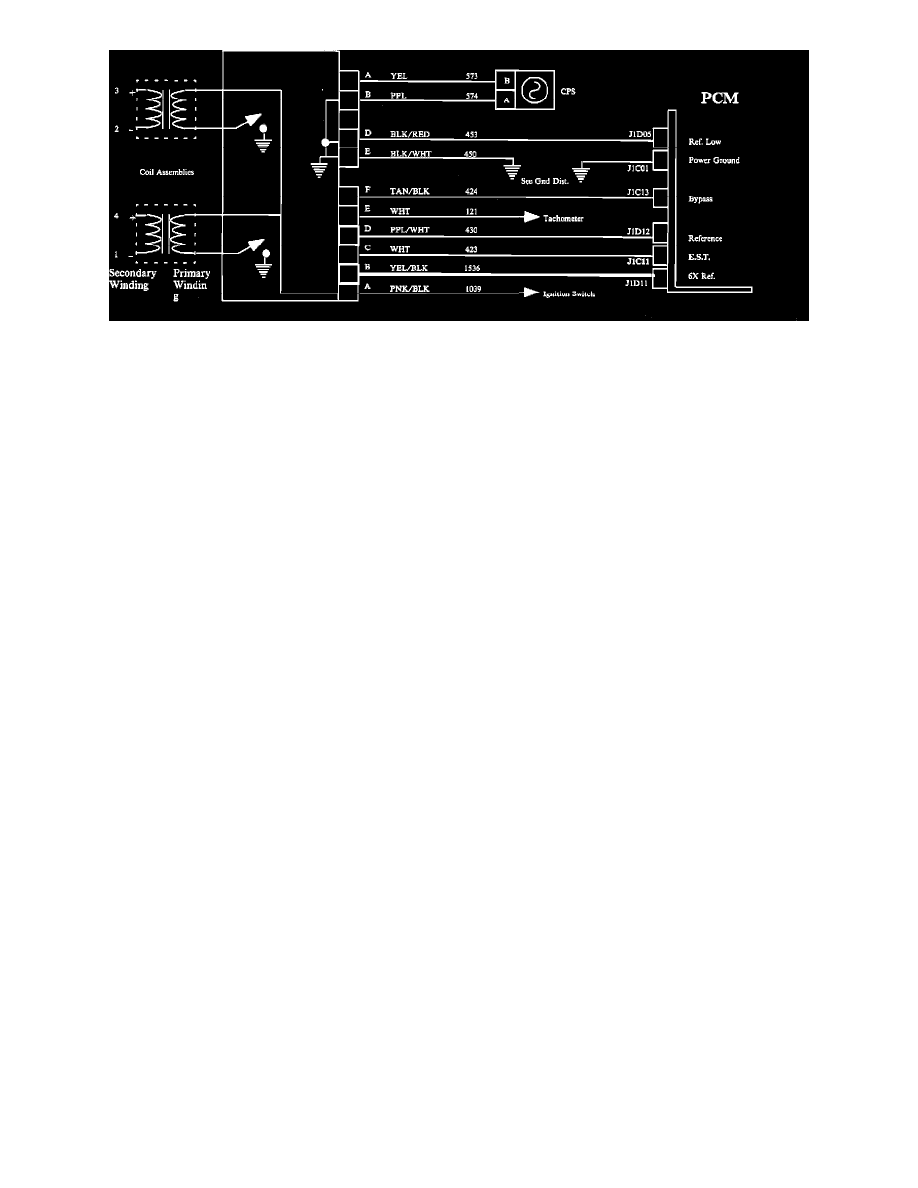
Ignition System Wiring.
VISUAL INSPECTION
^
Look for cracked or pinched wires.
^
Look for carbon tracks on wires.
^
Replace damaged wires.
^
Measure resistance of spark plug wires with no spark present.
- The measured resistance of the wires should be below 12k Ohms.
^
Replace faulty wires.
IMPORTANT: DIS ignition module and coils will be serviced as a complete assembly and should not be disassembled. When individual components
are released, the following diagnostic information must be followed to determine the specific component failure.
^
All wires check good.
^
Spark present on one coil only.
TEST TIP: To determine is the DIS ignition module is not triggering the problem coil or if the tested coil is at fault, switch positions of the coils. If the
problem did not move with the coil, the module is at fault.
DIAGNOSTIC AIDS
^
DIS module spark quick test:
^
Remove all four plug wires at the coil towers.
^
Have an assistant crank the engine. You should see sparks appear alternately between each pair of coil towers during cranking.
^
The DIS module, crankshaft position sensor and the coil packs are good if sparks appear between the coil towers.
CAUTION: The DIS system can produce extremely high voltages. Do not attempt to service this system while the engine is running or is being
cranked.
^
The measured resistance from tower to tower on the coils should be 7-10k Ohms.
^
The measured resistance of the crankshaft position sensor should be 700-900 Ohms.
^
To test for spark at spark plug wires use a spark test tool ST-125, or equivalent.
^
Engine firing order is 1-3-4-2.
^
Reversed CPS wires will result in a no start condition.