
SL L4-1.9L SOHC VIN 9 (1991)
Ignition Control Module: Component Tests and General Diagnostics
Diagnostic Charts
For information regarding Circuit, System, and Component diagnosis of solid state and/or computerized systems, refer to Computers and Control
Systems See: Computers and Control Systems/Testing and Inspection
DIS Module Spark Quick Test
DIAGNOSTIC AIDS
^
DIS module spark quick test:
^
Remove all four plug wires at the coil towers.
^
Have an assistant crank the engine. You should see sparks appear alternately between each pair of coil towers during cranking.
^
The DIS module, crankshaft position sensor and the coil packs are good if sparks appear between the coil towers.
CAUTION: The DIS system can produce extremely high voltages. Do not attempt to service this system while the engine is running or is being
cranked.
^
The measured resistance from tower to tower on the coils should be 7-10k Ohms.
^
The measured resistance of the crankshaft position sensor should be 700-900 Ohms.
^
To test for spark at spark plug wires use a spark test tool ST-125, or equivalent.
^
Engine firing order is 1-3-4-2.
^
Reversed CPS wires will result in a no start condition.
Spark at One or More Wires
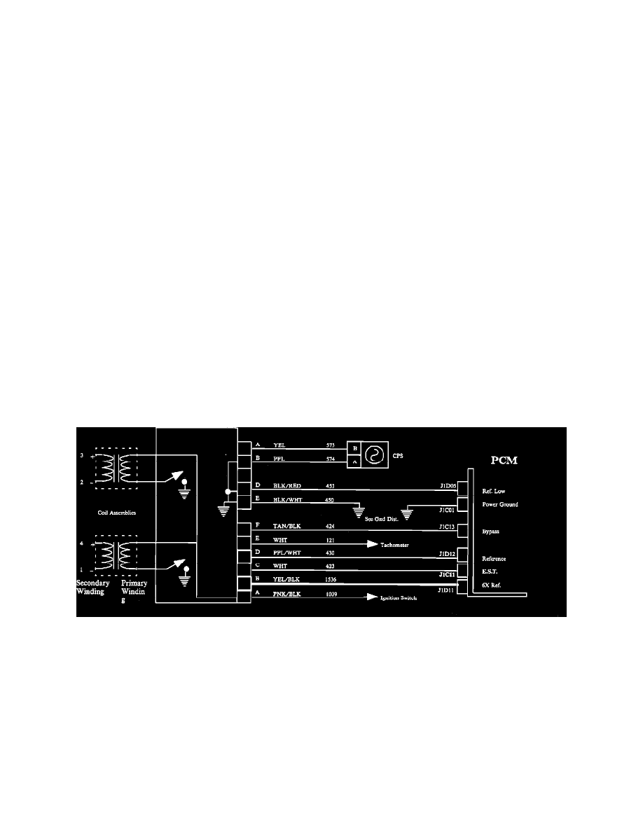
Ignition System Wiring.
NOTE: If no spark is present at any wire, refer to Chart I.
VISUAL INSPECTION
^
Look for cracked or pinched wires.
^
Look for carbon tracks on wires.
^
Replace damaged wires.
^
Measure resistance of spark plug wires with no spark present.
- The measured resistance of the wires should be below 12k Ohms.