
SW L4-1.9L DOHC VIN 7 (1993)
^
Splice TAN/ORN wire from delayed blower motor control module to length of ORN wire (circuit 52) that goes to HVAC blower control
switch
23.
Attach ring terminal lead kit (P/N 12112245) to BLK/WHT wire from delayed blower motor control module.
24.
Attach ring terminal on the BLK/WHT wire from delayed blower motor control module to ground location at H-brace. Make sure that new ring
terminal is on top of existing ring terminal.
Torque:
Ring Terminal-to-Ground: 2.2 N.m (20 in-lbs)
25.
Using a 1.5 m (5 ft.) length of .50 mm2 (20 gage wire):
IMPORTANT:
PCM 24-way connector is black for 1991 - 1992 DOHC and brown for SOHC, for 1993 and 1994 connector is Lt. blue for DOHC and pink for
SOHC.
25.1 At terminal J2B04 of PCM 24-way connector, splice one end of wire to DK BLU wire (circuit 604 [SOHC), 604A [DOHC]-A/C relay
control).
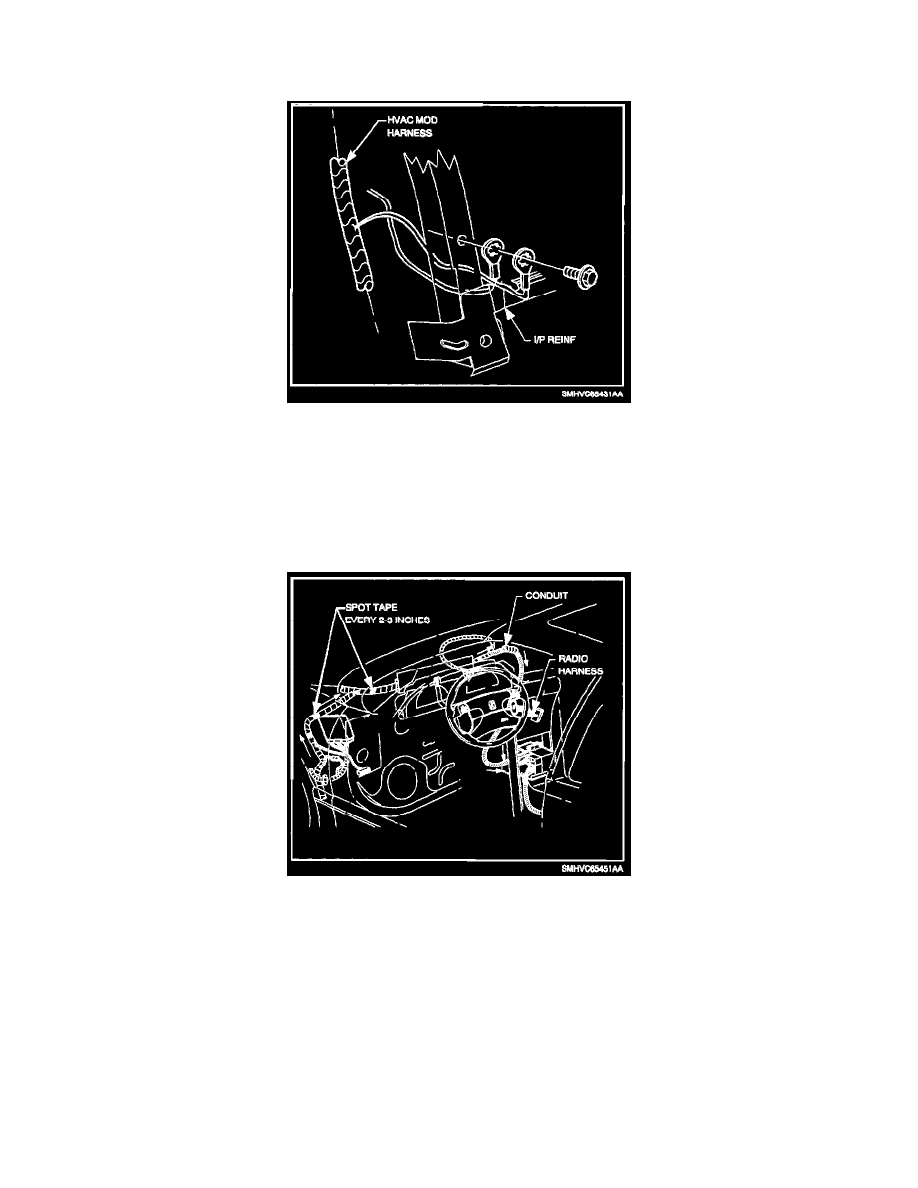
25.2 Route wire to the IPJB as follows (using electrical tape, spot tape wire to harnesses approximately every 51-77 mm (2-3 in.):
a.
Tape wire to DLC connector harness branch.
b.
From top of I/P, route wire between I/P harness splice packs and I/P harness channel.