
SW2 L4-1.9L DOHC VIN 7 (1997)
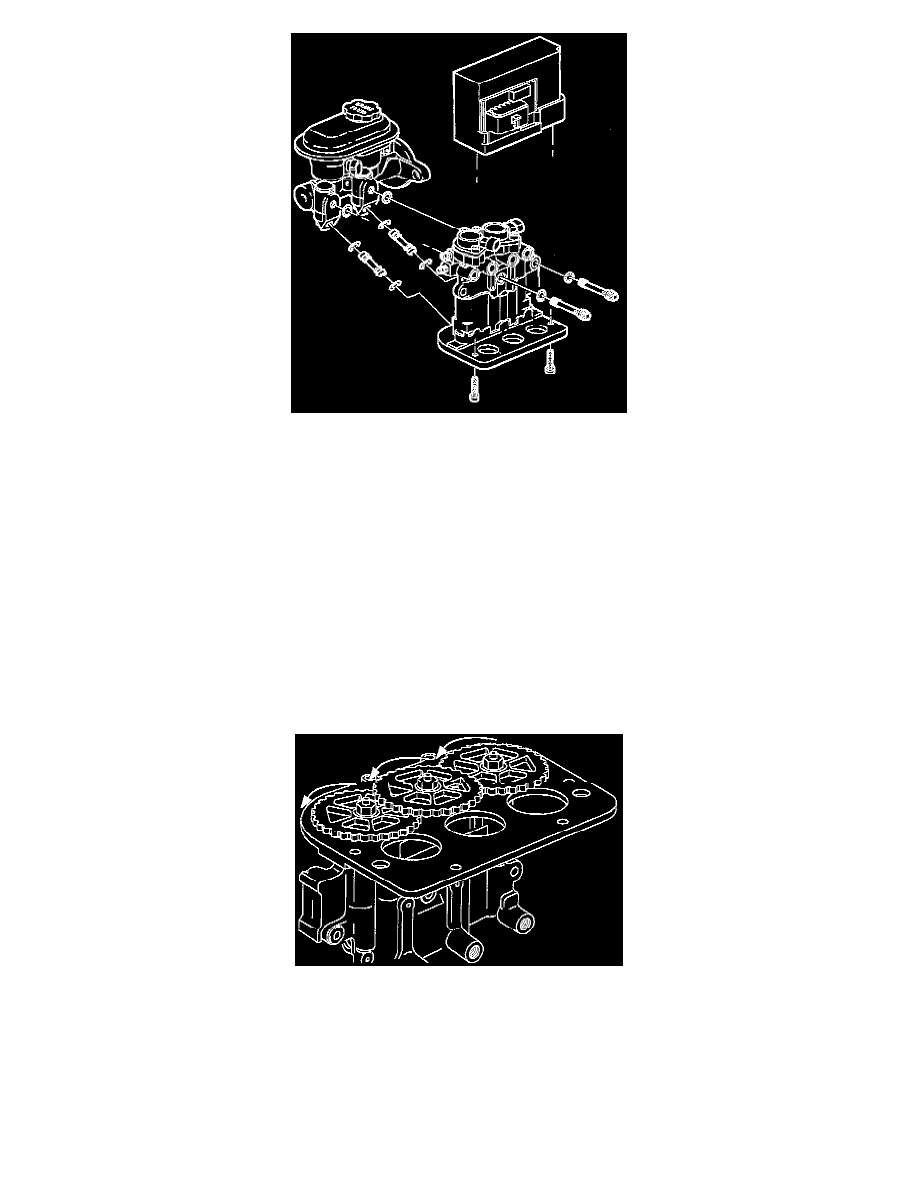
3. Remove two motor pack-to-modulator T0RX(r) head screws and separate motor pack from modulator.
4. Remove two modulator-to-master cylinder through-bolts and separate modulator from master cylinder.
5. Remove two transfer tubes with 0-rings from master cylinder or modulator.
6. Remove through-bolt 0-rings from master cylinder and modulator.
ASSEMBLY
1. Lubricate new transfer tube 0-rings with clean brake fluid.
CAUTION: New 0-rings and transfer tubes must be used when performing this step.
2. Install transfer tubes (with 0-rings) into modulator by pressing in tubes by hand, until bottomed in modulator.
3. Lubricate new through-bolt 0-rings with clean brake fluid and install into master cylinder and modulator.
4. Install master cylinder onto modulator.
5. Install two modulator-to-master cylinder through bolts.
^
Torque to 16.5 Nm (146 inch lbs.)
6. Position modulator drive gears onto drive shafts and install three gears to drive shaft retaining nuts.
^
Torque to 8.5 Nm (75 inch lbs.)
7. With the modulator upside down and the gears facing you, rotate each gear counter-clockwise until movement stops. This procedure will position
the pistons very close to the top of modulator bore, simplifying the brake bleeding procedure.
8. Position motor pack onto modulator aligning the three motor pack gears with the modulator gears and install two motor pack to modulator
T0RX(r) head screws.
^
Torque to 4.5 Nm (40 inch lbs.)
9. Install gear cover onto modulator assembly with two T0RX(r) head screws.
^
Torque to 2.75 Nm (25 inch lbs.)