
SW2 L4-1.9L DOHC VIN 7 (1997)
into ORN 0.35 sq.mm (22 gage) wire (circuit 340L-battery feed) from 68-way connector.
18.2 At terminal E10, splice, using a salmon (pink) splice sleeve, the RED 0.50 sq.mm (20 gage) wire from delayed blower motor control module
into BRN 0.35 sq.mm (22 gage) wire (circuit 641 A-ignition) from 68-way connector.
18.3 Connect black I/P harness connector.
Torque:
I/P Harness Connector: 2.2 N.m (20 in.lbs)
19.
Splice into the high blower relay coil ignition feed wire as follows:
19.1 Disconnect HVAC fan switch (blower control switch) electrical connector from the HVAC control head.
19.2 Detach the wiring harness clip (found attached to the HVAC module) so that wiring harness can be pulled rearward to make it easier to work
on the HVAC fan switch connector.
19.3 Route the TAN/ORN and BLK/ORN wires (from the delayed blower motor control module) up from the IPJB area, between the HVAC
control head and the HVAC module, to the HVAC control head area.
19.4 Locate the ORN wire found in cavity A of the HVAC fan switch electrical connector that goes to the blower relay. Cut the wire
approximately 51 mm (2 in.) from the HVAC fan switch connector.
19.5 Splice the in-line fuse ORN 2.0 sq.mm (14 gage) wire (P/N 21024696) to the HVAC fan switch connector side of the cut ORN 2.0 sq.mm
(14 gage) wire by using a blue splice sleeve.
19.6 Splice the in-line fuse TAN 0.80 sq.mm (18 gage) wire (P/N 21024696) to the TAN/ORN 0.50 sq.mm (20 gage) wire (one of the wires
routed up from the delayed blower motor control module in step 19.3), by using a salmon (pink) splice sleeve.
IMPORTANT:
When performing the following splice, make sure to double the thickness of the BLK/ORN .50 sq.mm (20 gage) wire by bending the wire in half and
twisting it before inserting the wire into the splice sleeve.
19.7 Splice the BLK/ORN .50 sq.mm (20 gage) wire (one of the wires routed up from the delayed blower motor control module in step 19.3) to
the harness end (that goes to the blower relay) of the ORN 2.0 sq.mm (14 gage) wire, which was cut in step 19.4, by using a blue splice
sleeve. (This splice should be performed in the HVAC control head area.)
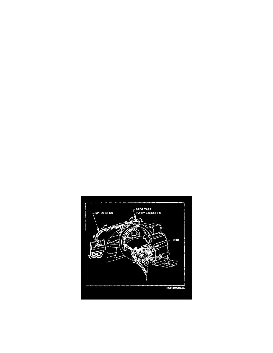
19.8 The in-line fuse will be routed to the top cover area by attaching it to the I/P harness as follows:
a.
Using electrical tape, spot tape the wires to the I/P harness approximately every 51-76 mm (2-3 in.).
b.
Starting at the HVAC fan switch area (blower control switch), attach the in-line fuse wires to the HVAC branch with a piece of
electrical tape.