
SW2 L4-1.9L DOHC VIN 7 (1997)
35.
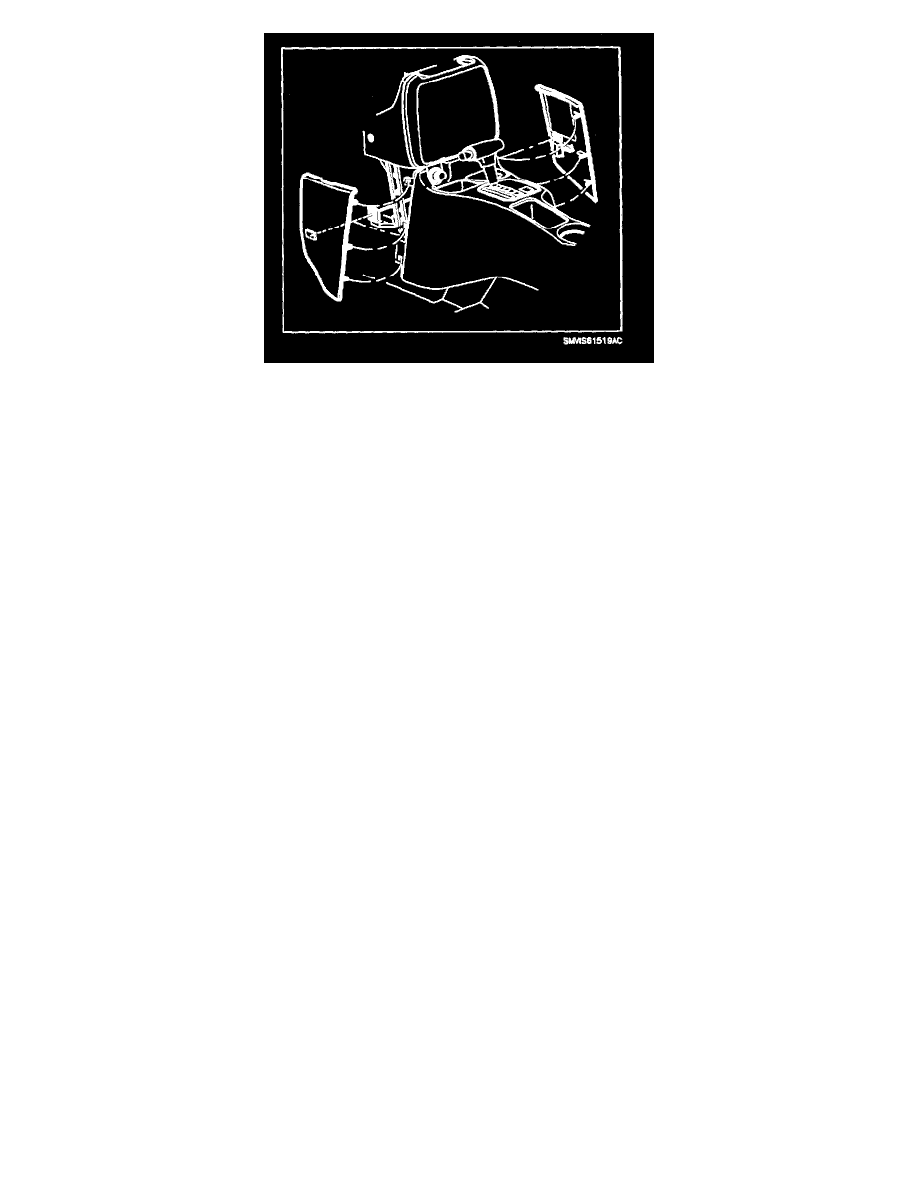
Install right and left console extension assemblies.
36.
Enable the SIR system. (Refer to "Enabling the SIR System" in the 1997 "SIR Service Manual.")
37.
Set radio station presets.
38.
Clear any SIR diagnostic trouble codes that may have set during delayed blower motor control module testing. (Refer to the 1997 "SIR Service
Manual.")
Wiring Splicing
With the wiring used in the Saturn vehicles, it is recommended that approved Packard Electric Crimp and Seal Splice Sleeves (or equivalent) be used.
1.
Remove insulation from both ends, recommended strip length is 9.5 mm (3/8 in.). Caution must be used to prevent cutting the wire strands.
Locate new splice a minimum of 40 mm (1-1/2 in.) from an outlet or other splice.
2.
Determine proper sleeve for gage of wire. Position stripped ends in sleeve until wires hit stop.
IMPORTANT:
When using the salmon splice sleeve with 0.35 sq.mm (22 gage) wire, remove 19 mm (3/4 in.) of insulation. Bend the stripped portion in half to
double the thickness of the wire going into the splice sleeve. Twist the stripped, doubled wire and insert into the splice sleeve.
IMPORTANT:
When splicing three wire ends into one splice sleeve, insert one cut wire end from vehicle harness and new splice wire end into one side of the splice
sleeve until wires hit stop. Hand crimp using approved crimping tool. Insert remaining cut wire end from vehicle harness into other side of splice
sleeve and crimp.
3.
Hand crimp sleeve using the approved crimping tool. Gently tug on wires to make sure they are secure before applying heat to them.
CAUTION:
DO NOT USE A MATCH OR OPEN FLAME TO APPLY HEAT TO SPLICE SLEEVE.
4.
Apply heat using Ultratorch(R) (or equivalent), heating splice sleeve to 175° C (347° F). Heat until glue flows around edges of splice sleeve.
5.
Check for continuity in the wire.
Testing the Delayed Blower Motor Control Module
A full functional check of the delayed blower motor control module is required to assure that all electrical connections are connected properly and it is
functioning as designed.
1.
Locate the GRN wire at cavity H of the delayed blower motor control module and insert a metri-pack 280 series male test adapter into cavity H
until contact is made with GRN wire terminal in the delayed blower motor control module pigtail connector.
IMPORTANT:
Do not disconnect the jumper harness connector from the delayed blower motor control module pigtail connector or system test will not function.