
SW2 L4-1.9L DOHC VIN 7 (1997)
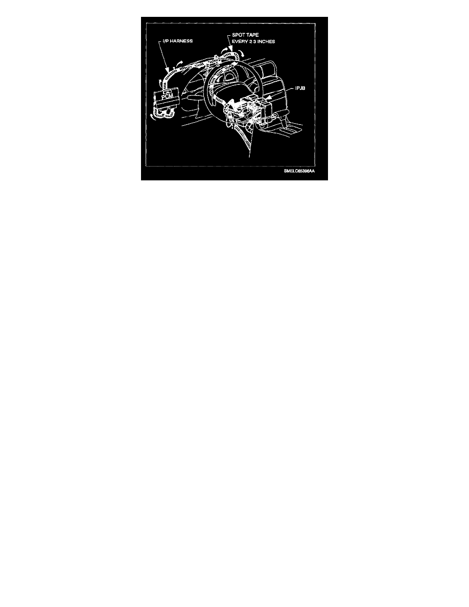
23.2 Route wire to the IPJB as follows (using electrical tape, spot tape wire to harnesses approximately every 51-76 mm [2-3 in.]).
a.
Tape wire to PCM branch of I/P harness.
b.
Follow harness up to I/P splice packs, forward of PCM.
c.
From top of I/P, route wire along I/P harness, following the main branch across, forward of beam, and then down to IPJB. Route wire
to the left of cruise control connector (if equipped).
23.3 Splice 0.50 sq.mm (20 gage) wire to WHT 0.50 sq.mm (20 gage) wire from delayed blower motor control module using a salmon (pink)
splice sleeve.
23.4 Connect PCM Lt. Blue 32-way connector.
24.
The BLU wire from the delayed blower motor control module is unused. Tape end of BLU wire and tape back to jumper harness of delayed
blower control module. The delayed blower motor control module GRN wire is used for testing.
25.
Attach top half of "Notice" label provided i~n kit to blower motor cover. Attach bottom half of "Notice" label to inside of right side console
extension assembly.
26.
Connect black I/P harness connector.
27.
Connect negative battery cable.
Torque:
Battery Cable: 17 N.m (13 ft-lbs)
IMPORTANT:
Do not install parts that have been removed, except for black I/P harness, until correct operation of the delayed blower motor control module has
been verified.
28.
Proceed to "Testing the Delayed Blower Motor Control Module" and verify operation. After operation is verified, proceed to next step.
29.
Install radio.