
SW2 L4-1.9L DOHC VIN 7 (1997)
IMPORTANT: Once the probe is installed, it should not be removed. The diagnostic service probes were designed to stay on the wires permanently.
The gel material inside the probe will seal the wire and allow the wire to be probed several times.
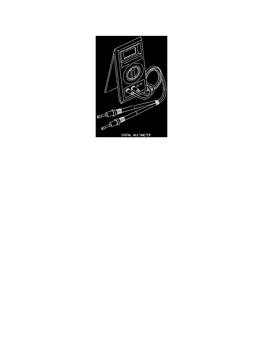
Digital Multimeter
Digital Multimeter
Digital multimeters approved for use on Saturn vehicles must have an input impedance of ten megohms (10,000,000 ohms). Input impedance is listed in
the multimeter's owner guide.
IMPORTANT: The input impedance of a multimeter stands for the resistance between the red and black leads, only when you are measuring voltage.
When measuring resistance, the only resistance other than in the circuit being measured is in the actual leads being used.
A digital multimeter performs all the tests that a test light can perform, with a greater degree of accuracy. In addition, a multimeter can be used to test for
current flow in a circuit.
IMPORTANT: Always follow the manufacturers recommendation when checking for current. All multimeters have a maximum current rating, do not
exceed this rating. Not all multimeters contain a fuse that protects the multimeter from damage if a larger current draw is experienced. So be careful
when checking for current draw.
Voltage
Voltage is the electrical pressure in the circuit and is the most commonly used electrical test setting on the multimeter. Most digital multimeters have a
number of different voltage scales. To determine what scale to use, always use the lowest scale on the multimeter that can be used to test the circuit. For
example, if the multimeter has a 200 millivolt scale, a 20 volt scale and a 200 volt scale, and you are testing for battery voltage (approximately 12-14
volts), set the multimeter to the 20 volt scale. If you should select a scale that is too low, the meter indicates this by displaying a 1 or an OL on the
display. This will not harm the multimeter, and you can always select a higher scale until a good reading is obtained. The same goes for selecting too
high of a scale. If you select the 200 volt scale and you are testing for battery voltage (12.8 volts), most multimeters will display 12 volts. By selecting
the next smallest scale, 20 volts, the multimeter's display will change to 12.8 volts.
Amperage (Current)
Since a multimeter has a very low resistance when measuring current, caution must be used to prevent damage to the multimeter. Always check the
recommendations, listed in the multimeter's owner guide for the maximum current to be tested for. As previously mentioned, most multimeters are
protected by a fuse when checking for current. However, not all multimeters are protected, and excessive current will damage a multimeter.
The most common use for measuring current in automotive applications is checking for parasitic current drain. This is the amount of current being drawn
by the vehicle with all electrical loads off. The normal parasitic current drain for a Saturn vehicle is less than 10 milliamps (although it can go as high as
14.1 milliamps if the vehicle has the Saturn approved anti-theft system installed). This current drain comes from components that require voltage to
sustain a memory circuit such as the clock, radio, powertrain control module, etc. However, when checking for parasitic current drain, always check to
see if the customer has installed any non-factory installed items that could require constant voltage such as a cellular phone, anti-theft system, etc.
IMPORTANT: The ignition key must be removed from the cylinder before parasitic load testing. The key reminder circuit is activated by the key
cylinder switch when the key is in the ignition cylinder, which adds 20 milliamps of current draw.
In the "Parasitic Load Testing," two methods will be explained for testing a vehicle for parasitic loads. One method is with the Saturn Parasitic Load